10 Implementation Guides
10.3 Installing Plant Materials
Once the project site has been prepared (See Section 10.1, Soil and Site Treatments) and the plant materials have been obtained (See Section 10.2, Obtaining Plant Materials), the vegetation can be installed on the project site. The following implementation guides cover the methods for installing seeds, cuttings, and plants. Section 10.3.1, Seeding, discusses the different methods of seeding, how to formulate seed mixes, determining seeding rates, and assuring quality. A specialized form of seeding, hydroseeding, is discussed in Section 10.3.2. Section 10.3.3, Installing Cuttings, outlines cutting installation techniques most commonly used in biotechnical engineering designs. Section 10.3.4, Installing Plants, discusses techniques for planting bareroot and container plants. It also discusses seedlings, plant handling, storage, and quality control measures.
10.3.1 Seeding
10.3.1.1 Introduction
Seeding is the distribution of seeds for the purpose of establishing seedlings at a desired density and species composition. Optimal seeding operations must take into consideration: 1) how seeds are uniformly distributed over an area, 2) where seeds are placed vertically (that is, in, on, or under the soil surface), 3) species composition in the seed mix, and 4) when seeding takes place. These factors must be adapted to each revegetation unit to account for the unique climate, soils, and species requirements of each site.
Seeding is often coupled with other operations, such as fertilization, soil amendment applications, and soil stabilization treatments. While accomplishing these objectives at the same time as seeding often makes practical sense from an economic and scheduling standpoint, it might not always be best for the short-term establishment of native vegetation. It is important to consider the effects of combining too many operations into the actual sowing operation. It may be necessary to plan some of these operations at different times. For example, fertilizing, which is often done during the seeding operation, might best meet objectives if applied separately from seeding (See Section 10.1.1).
This section will cover the different steps in developing a seeding plan: 1) identifying seeding areas, 2) determining seed application methods, 3) developing seed mixes, 4) determining sowing rates, 5) preparing seed mixes, 6) selecting sowing dates, and 7) applying seed and assuring quality.
10.3.1.2 Identify Seeding Areas
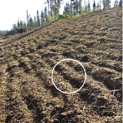
It is important to visit the project site as soon after road construction as possible and specifically identify seeding areas on the ground. If road construction is a multi-year project, finished slopes should be assessed for seeding while the remaining construction continues. While most of the seeding areas will conform to the revegetation units developed during planning, sites always look different after construction. A field review should note where topsoil has been placed, presence of surface rock, surface roughness, accessibility by equipment, microclimate, soil compaction and other site factors. These factors will be used to develop: 1) seeding methods, 2) sowing dates, 3) seed mixes, and 4) seeding rates for each of the seeding areas.
Seeding areas are located on a map and by road station. For each seeding area, acreage can be calculated using methods described in Figure 9.2 in Chapter 9, Implementation. These calculations must consider the areas where seeding will actually take place. For instance, seeds should not be applied in areas where herbicides will be used for maintenance. At the end of the field survey, total acreage for each seeding area will be summarized and this information will be used in developing seed mixes for each seeding area (See Section 10.3.1.6 and Section 10.3.1.7).
10.3.1.3 Determine Seeding Methods
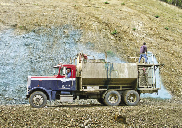
There are a variety of methods for applying seeds available to the revegetation specialist. The challenge is matching these methods to the sites encountered in mountainous terrain. Typically, the site characteristics of each seeding area will dictate the type of seeding method used. For example, a road project has three revegetation units — a steep, north-facing slope; an obliterated road; and a rocky south slope. Hydroseeding could be planned for the steep, north-facing slope where other equipment cannot reach. On the obliterated road, several ground based seeding methods could be used, including mixing seeds into the soil, or broadcasting on the surface and covering with a mulch. The south-facing slopes could be hand-seeded or hydroseeded, then covered by a mulch to keep the seeds from drying out during germination. Each project needs to approach seeding with a strategy that is the most efficient and will provide optimal conditions for seed germination.
Each species has a unique seed covering requirement. While seeds of most species must be buried in the soil or covered by mulch to germinate, some species actually require some exposure to light to germinate and must not be covered very deeply. A general rule for seed covering is to bury seeds at depths from twice (Munshower 1994) to three times (Monsen and Stevens 2004) the seed diameter. The deeper the seeds are covered, the less likely they will dry out during germination. The tradeoff, however, is that seedlings will have to expend more energy to emerge from deeply buried seeds. This can ultimately affect early seedling establishment.
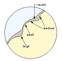
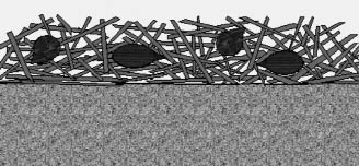
The ideal seedbed, as defined by Monsen and Stevens (2004), is "one in which the seed is firmly enclosed within soil particles to provide hydraulic conductivity of moisture to the seed. Seeds should be placed deep enough to prevent rapid drying but shallow enough to allow natural emergence." Creating an ideal seed environment is an important practice, especially in nurseries, farms, or gardens where the objective is to create a uniform plant crop. All operations in these settings must be standardized and uniform (e.g., correct seed depth, optimum lighting, uniform irrigation, uniform seed densities, etc.). While uniformity and standardization can be applied to wildland revegetation, an alternative strategy might be considered. This strategy starts from the premise that we really cannot know much about the specific germination and early seedling growth requirements of different native species at each seeding site. For this reason, we should be creating a variety of environments, or "regeneration niches" (Grubb 1977), where seeds might find the right conditions for germination (Figure 10.86). Further, we should apply a range of native species to fill these environments. With wildland revegetation, uniformity is not the objective. In fact, non-uniformity will most likely fit with the surrounding plant communities.
Vertical seed placement, where seeds are vertically distributed in soil or mulch layers, can be grouped into the following categories:
- Broadcast onto the surface,
- Pressed into the soil surface,
- Mixed under the soil surface,
- Drilled under the soil surface,
- Covered with long-fiber mulch,
- Mixed into long-fiber mulch, and
- Mixed into hydromulch.
Vertical seed placement methods will be discussed in the following sections in the context of how they affect germination and seedling establishment.
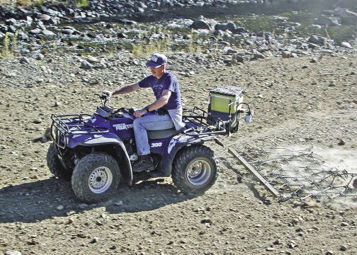
Seeds Sown on the Soil Surface — One of the most common forms of seeding is broadcast seeding, which is casting seeds on the surface of the soil with a rotary spreader or by hand. Broadcast seeding is almost always the least expensive form of seeding. Rotary spreaders can be attached to most types of vehicles, including all-terrain vehicles and pickups, and used where vehicle accessibility is good. Where slope gradient or accessibility limits mechanical seeding, using a hand-held broadcast seeder is an option. While manual broadcast seeding might be considered a very low-tech method, it still has an important place in revegetation.
Manual broadcast seeding offers the opportunity to spot-seed microsites at different seed rates and seed mixes. For example, two people could hand seed a steep cut slope requiring two different seed mixes — the lower portion of the slope sown with a grass and forb seed mix and the upper portion with a shrub and seed mix. In another instance, a fill slope composed of rocky outcrops interspersed among deep soils has two distinct microsites that could be seeded separately with different seed mixes. With knowledge of the road objectives, several hand seeders can apply seeds across a project area that mimics the vegetative patterns of the landscape. Spot-seeding can also be a method of applying valuable seeds or "unique" species to strategic locations. For instance, showy forbs that are expensive to obtain or require a specific habitat can be spot-seeded in those locations.
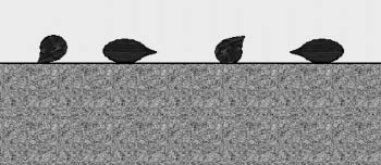
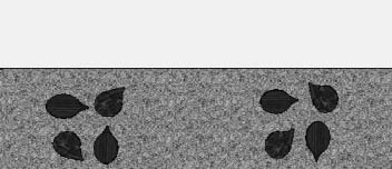
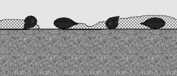
The disadvantage of broadcast seeding is that seeds are not covered by soil or mulch (Figure 10.87). Since seeds need intimate contact with the soil to germinate, broadcast seeding typically leads to low establishment of seedlings. If greater quantities of seeds are sown; however, some seeds will find microsites with high humidity (between surface gravels or rock) or will be covered by soil particles that have been moved through erosion processes. Estimates of 50% to 75% more seeds must be sown to compensate for the inability of seeds to germinate or the loss of seeds to rodents (Monsen and Stevens 2004). Survival factors must be adjusted downward when calculating sowing rates for seed mixes (See Section 10.3.1.6). Broadcast seeding on roughened surfaces can potentially increase germination rates, especially if seeds are sown in the fall. The probability that seeds will be covered by sloughing soil over time is increased (Stevens and Monsen 2004), so it is important that the soil surface be left as rough as possible where broadcast seeding will be used.
| Figure 10.87— Broadcast seeding leaves seeds exposed on the soil surface where they are not in contact with the soil. |
 |
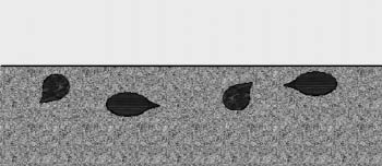
Seeds Pressed into the Soil Surface — Seed that is sown on the surface and pressed into the soil increases germination rates over broadcast sowing. Seeds are in firm, intimate contact with the soil, which increases available water to the seeds (Stevens and Van Epps 1984) (Figure 10.88). Imprinting produces a variety of microsites which may benefit the germination of a mix of species (Stevens and Monsen 2004). This type of seeding is accomplished with imprinting equipment (See Section 10.1.2.4). In this operation, seeds are dropped from a seeder mounted in front of the imprinter and then pressed into the soil. Imprinting works well for small to medium sized seeds; seeds are in firm contact with the soil but not buried too deeply to affect seedling emergence. In some cases, imprinting small- and medium-sized seeds can result in germination as good as, or better, than drilling seed (Haferkamp and others 1985). Larger seeds must be covered by soil or mulch for adequate germination. Imprinting seeds cannot occur on steep slope gradients or slopes with high rock content. Sites that are too steep for tractor access are too steep for current imprinting equipment.
| Figure 10.88 — Pressing seeds into the soil surface improves germination by increasing soil contact. |
 |
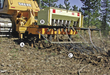
Seeds Mixed Under the Soil Surface — Mixing seeds into the surface of the soil is one of the best ways to achieve optimum germination (Figure 10.89). Mixing is done in two stages — seeds are applied on the soil surface by either broadcast seeders or by using a seedbox and drop tubes; seeds are then incorporated into the soil by dragging anchor chains, disk chains, cables, pipe harrows, or other implements behind a tractor. Equipment has been developed for wildland conditions that will seed and incorporate in one operation. The "ripper-seeder-harrow" (Figure 10.90) is a specialized seeder that subsoils, broadcasts seeds, and mixes in one operation. Use of this equipment is limited to slope gradients of 3H:1V or less and non-rocky soil surfaces.
| Figure 10.89 — Seeds mixed under the soil surface puts them in direct contact with the soil, greatly improving germination. |
 |
When mixing seeds into the soil on steeper slopes, any method that scarifies the soil surface after seeds have been broadcast will mix the seeds into the surface. Using a hand rake to incorporate broadcast seeds into the surface works well, and can be used in areas where expensive or valuable seeds have been applied. This type of seed placement requires that the seed depth be monitored to assure that it is not buried too deeply. Seeds should not be mixed deeper than one inch.
These application methods allow seeds to be mixed evenly through the soil and not concentrated in rows, as they are with drilling (see below). However, soil is left loose around the seeds, which decreases water-holding capacity. If seeds are sown in the fall and do not germinate until the following spring, natural packing of soil around the seeds will occur.
Seeds Drilled Under the Soil Surface — Using a seed drill is another method for covering seeds with soil. Seeds are not actually drilled into the soil, as the name implies, but sown just under the surface in rows. Seed drills 1) open the surface of the soil with a disk or tine; 2) drop seeds from a seedbox, through tubes, into the open furrows; 3) close the furrows with a disk; and 4) pack the soil firmly around seeds with a press wheel. Cropland drills have been developed for the agricultural industry. However, this equipment has limited applicability on highly disturbed sites because rocky soils and uneven soil surfaces create difficulties in placing seeds at proper soil depths. Several drills have been developed for rangeland restoration that compensate for these limitations. The Rangeland and Truax® drills were specifically developed for seeding rocky, uneven surfaces. The Truax® drill was an improvement on the Rangeland drill, and includes three seed boxes that can independently distribute seeds at different depths corresponding to the size and shape of the seeds (Stevens and Monsen 2004).
Seed drills concentrate seed into rows (Figure 10.92), creating a greater potential for competition between emerging seeds within rows than if seeds were broadcast. For example, a seed mix with an aggressive species will emerge and dominate the row of seeds at the expensive of less aggressive species. The three seedboxes on the Truax® seed drill can be used to compensate for this potential problem. The less aggressive species are placed in separate seedboxes and sown in separate rows. If more than one seedbox is used, separate sowing rates must be calculated for each box. Typically, lower seed rates are used in drilling operations because the seeds are concentrated in rows and closer together. Where rodents are present, drilled seeds are more prone to being excavated by rodents that simply follow a row of seeds (Stevens and Monsen 2004).
| Figure 10.92 — Seed drills place seeds in rows under the surface where they are in direct contact with the soil. |
 |
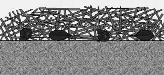
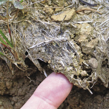
Seeds Covered With Long-Fibered Mulch — Optimum seed germination is obtained under long-fibered mulch. The mulch provides a moisture barrier that protects seeds and keeps soil from drying (Figure 10.93). Soil moisture is maintained longer around seeds than if they were strictly covered by soil. This is a two-stage operation in which seeds are broadcast on the soil surface and then covered by mulch. The thickness at which the mulch is applied depends on the seed size and the type of mulch. Small seeds will require less cover than large seeds. The rate at which mulch can be applied varies by the characteristics of each type of mulch. Wood strands and straw, for instance, can be applied at higher rates (thicker layers) than composts or chips because more light is able to penetrate these mulches, allowing seed germination and seedling establishment. See Section 10.1.3 for further discussion of mulches.
| Figure 10.93 — Covering broadcast seeds with long-fibered mulch is very effective in conserving moisture around the seeds. |
 |
Sowing seed mixes that contain a variety of seed sizes will require that the mulch not be uniformly applied. One strategy is to begin with a roughened seedbed as shown in Figure 10.86. Because the surface is not even, mulch will settle in depressions and be thicker than on the ridges. Monitoring the application rates is important to assure that seeds are covered with the proper mulch thickness. While covering seeds with long-fibered mulch is the most favorable method for optimum seed germination, it is also the most expensive.
Seeds Mixed into Long-Fibered Mulch — Seeding and mulching are often combined into one operation (Figure 10.94). Most mulch blowers have seed metering systems which distribute seeds with the mulch as it is being applied to the soil surface. Seeds in this operation are distributed within the mulch, as opposed to being placed between the soil surface and mulch layer. Although one operation is more efficient, seed germination and seedling emergence rates are typically lower than when seeds are broadcast on the surface and covered with mulch. Seeds are not in contact with the soil when mulch and seed are mixed. Unless the mulch has a high water-holding capacity, moisture around the seeds will be limiting during germination and seedling emergence. It is important to know how much moisture a mulch can hold when deciding whether seeds will be mixed with the mulch or broadcast applied first then covered with mulch (See Section 5.2.2.1 for determining moisture holding capacities of mulches). Composts, for instance, have high water-holding capacities, and seeds will germinate well in this material; ground or shredded wood mulch and wood strands have very little water-holding capacity and seed germination will be poor. Seed rates should increase relative to how much moisture the mulch is expected to hold. For low water-holding capacity mulches, seeds in the upper portions of the mulch will not germinate or will germinate poorly. Seed rates in this type of mulch should be increased by 25% to 50%.
| Figure 10.94 — Seeds mixed into long-fibered mulch have less contact with soil, which can reduce germination. |
 |
Seeds Applied in Hydromulch — When seeds are applied through a hydroseeder (See Section 10.3.2), they will lay on the soil surface surrounded by a thin covering of fine-textured wood fibers (Figure 10.95). At rates of 1,000 lb/ac hydromulch, seeds will be covered with less than 0.25 inch of mulch, with some seeds not covered. As rates approach 3,000 lb/ac, mulch thickness increases to over 0.25 inch, with most seeds being covered. Hydromulch has a high water-holding capacity, maintaining up to two and a half times its dry weight in water. This can be beneficial to seeds during germination. However, unless very high rates of hydromulch are applied, many seeds in the slurry are not covered by the hydromulch. Some hydroseeding operations try to compensate for this by applying a slurry containing seeds first, and covering the seeds with hydromulch with a second pass. The thin seed cover is favorable for only small seeded species. Seeds can be damaged in the hydroseeding operations through the pumps and agitators, or by hitting the ground at very high speeds during application.
| Figure 10.95 — Applying seeds in a hydromulch places a portion of seeds on the soil surface and some suspended in the hydroseeding matrix above the surface. |
 |
Even with these limitations, hydroseeding is still one of the most common methods of applying seeds to road construction disturbances. It is often the only way to place seeds on steep, rough terrain encountered in mountainous regions. Compensation for these limitations has had varying degrees of success. Possible variations include: 1) increasing the amount of seeds, 2) applying seeds in the first pass, then covering with hydromulch in the second pass, and 3) applying higher rates of mulch. Fall hydroseeding also increases establishment rates. Over-wintered seeds are ready to germinate on the first warm days of late winter or early spring when humidity levels are high. In addition, hydraulic mulches are more likely to stay moist for longer periods of time. Hydroseeding is simpler than dry seeding because there is no seed metering system; seed mixes are simply mixed into the hydroseeder tank and applied. See Section 10.3.2 for more discussion on hydroseeding.
10.3.1.4 Formulate Seed Mixes
The seed mix refers to the species composition being applied over a seeding area. It is important to avoid applying a single species to a site. Since highly disturbed sites typically are extremely variable in soil temperatures, fertility, soil moisture, solar radiation, and other site factors, it is important to apply a number of species in a seed mix to assure that all possible microsites are populated (Monsen and Stevens 2004). Microsites that are unfavorable to one species might be favorable to others. Applying a mix of species also assures that if there is a problem with the germination of one species, the other species will fill in. The composition of seed mixes and sowing rates should be based on the growth habits of each species and the soils and climate of the site.
It is preferable to avoid mixing slow-growing species with fast growers, because the fast growers will out-compete the slow growers for space and resources (Monsen and Stevens 2004). Separating slow growers from fast growers is not always possible. The seed quantities must therefore reflect higher ratios of slow growers to fast growers to achieve some degree of success. Shrubs and trees are typically less aggressive than grasses during the establishment phase, and should be applied in a separate mix or planted as seedlings. Grasses tend to be more aggressive than forbs. However, if the Truax® seed drill is used, they could be applied in the same area but in different rows using the separate seed boxes. Some species take several years to develop. A mixture of fast-growing annuals and slow-growing perennials will assure that there is cover the first year, yielding to more robust perennials in the succeeding years.
Disturbed reference sites can be good indicators of species that are adapted to the climate and soils of the project area. Vegetative surveys conducted during the planning stages should show the proportions of species that can be expected, and these findings should become the basis for developing species composition and ratios of each species. Prior to determining sowing rates, the proportion of each species within each seed mix should be set. This information will be used to determine seeding rates for each species.
10.3.1.5 Determine Sowing Rates
The sowing rate is the amount of seeds of each species in a seed mix that are applied in a given area. Sowing rates are calculated for each species that compose a seed mix. These calculations are performed twice — once during the development of seed increase contracts to obtain an approximate quantity of seeds to propagate for the entire project, and several months prior to actual seeding when seed inventories are known and exact seeding areas are located. The calculations made prior to seeding will be used to assemble the seed mixes for each seeding area.
Each species requires a set of data to calculate the total pounds of seeds needed in a seed mix which includes:
- Pure live seeds per pound of bulk seeds,
- Estimated first year survival,
- Target first year seedling density for all seeded species,
- Percentage of density composed of each species, and
- Area that will be seeded with seed mix.
Figure 10.96 shows one method for calculating the amount of seeds needed of each species in a seed mix. Since a seed mix is made up of several species, calculations must be performed on each species. In this example, blue wildrye (Elymus glaucus) is one of several species included in a seed mix. The end result of these calculations is the number of pounds of blue wild rye seeds that must be added to each seed mix bag.
Pure Live Seeds Per Pound (PLS/lb) — When purity and germination are multiplied together and divided by 100, the resulting value is the % pure live seeds (PLS). It represents the percentage of the gross seed weight that is composed of viable seeds (See Figure 10.65 in Section 10.2.4). For example, if germination is 89% and purity is 92%, the PLS would be 82%. When PLS is multiplied by the number of seeds per pound, the result is the pure live seeds per pound of gross seeds (PLS/lb). This value is often used in seed and sowing calculations, and it states the approximate number of seeds that will germinate in a pound of gross seeds under ideal (test) environments. For example, the PLS in Figure 10.96 is 82%, and the number of seeds per pound is 128,000. The total PLS/lb is (82/100) * 128,000 = 104,806 (Line D in 10.96). Tests for purity, germination, and seeds per pound are run by State Certified Seed Testing Laboratories and obtained from the seed producer or supplier.
First Year Survival — Not all viable seeds develop into established seedlings after being sown on a disturbed site. The conditions encountered on revegetation sites are generally unfavorable for germination and plant establishment. The first year survival factor reflects the effect of the harshness of the site on plant establishment (Line E of Figure 10.96). It is a prediction of the percentage of PLS that germinate and become established plants after the first growing season. A favorable site, for instance, will have a high survival factor because a high percentage of live seeds will germinate and establish into plants; a harsh site will have a low first year survival factor because seeds will germinate poorly, resulting in plants less likely to survive over the dry summer months. Unfortunately, there are currently no established field survival factors for the western United States. Therefore, the revegetation specialist will have to make estimates based on experience and an understanding of site factors, seed handling, and sowing methods.
How much fall down actually occurs? Even under very controlled growing environments, such as those found in seedling nurseries, survival factors are much lower than most would think. It is not uncommon for bareroot seedling nurseries to set first year survival values between 65% and 75% (USFS 1991). Compare the highly controlled environment of a nursery to seeding in the wild, where precipitation is intermittent and soils are depauperate. It should be no surprise to find that only 10% to 20% of the live seeds sown in the wild actually turn into live plants the first year after seeding (Monsen and Stevens 2004; Steinfeld 2005).
Estimating the first year survival is always a guess. It is interesting that very exact data from seed tests are used for a portion of the sowing calculations, followed by a broad approximation of how well viable seeds will actually germinate and become established in the field. Unfortunately, this information is hard to obtain. Monitoring data collected in the spring and fall, after the completion of each seeding project, can be used to develop a basic understanding of how seeds perform in the field under various soils, climates, and mitigating treatments. First-year monitoring that measures seedling density is useful in this regard. The number of seedlings can be counted in a series of photoplots, and the average number of seedlings per square foot can be calculated. The average seedling density, divided by the average number of PLS sown per square foot (line H of Figure 10.96), gives the survival factor for that project area. Steinfeld (2005) performed this type of monitoring for several seeding projects six months after sowing on southwest Oregon sites and found the results to be very low (15% of viable seeds became established plants). If this type of assessment is conducted over a range of seeding projects, survival factors could be developed for a range of soil and climate conditions. It would be good to understand how survival factors change with different types of seed covering methods.
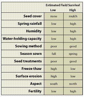
Factors to consider when estimating survival factors are shown in Table 10.16. Chapter 5 discussed how these factors affect plant growth. Sites with low first year survival would have a large number of limiting factors. Very poor sites can have survival factors below 5%, whereas favorable sites can have factors as high as 20%.
Target First Year Seedling Density — The target first year density is the number of plants/ft2 desired the first year after sowing (Line F of Figure 10.96). Establishing target density factors is often based on the objectives of the project. For example, projects where the objective is fast plant establishment for either erosion control or weed prevention would usually require the target first year densities to be relatively high. Target densities are also based on the growth habits of the species to be sown. Fast-growing species with large spreading growth habits would have low target densities. Shrubs and trees would have target first year densities of less than 1 plant/ft2, whereas grasses might have densities up to 25 seedlings/ft2. Monitoring sites after one year can give a good indication of what densities can be expected from each species and what densities are most appropriate for meeting project objectives.
It should be recognized that there is a point of diminishing returns, where applying more seeds does not necessarily produce more seedlings. There is a limit to how many seedlings can survive on a site, and no amount of seeds applied will change this fact. While applying excess seed errs on the conservative side, it can be wasteful and costly. It can also favor the aggressive species over the less aggressive species (Monsen and Stevens 2004). When using high seeding rates, it is important to reduce the ratio of aggressive species to non-aggressive species in order to assure that non-aggressive species can become established.
Target Composition — The target composition is the proportion of each species that will comprise the seedlings found in a given area (Line G of Figure 10.96). An example of a target seed mix composition is one that would produce a stand of grass and forb seedlings made up of 35% blue wildrye (Elymus glaucus), 35% California fescue (Festuca californica), and 30% common yarrow (Achillea millefolium). See Section 10.3.1.4 for further discussion.
Area to Seed — The area to seed is the total acreage of a seeding area to which a seed mix will be applied (See Section 10.3.1.2 for a discussion on how seeding areas are determined.)
10.3.1.6 Prepare Seed Mixes
Once sowing calculations are completed for each species, seed mixing operations can begin. The objective of these operations is put together seed mixes in packages that are organized, easy to handle, and ready to use. This is an important step, because there can be no room for confusion in seeding operations or time for reorganizing seed mixes. The seed mixing operation involves weighing seeds from each species or seedlot, mixing seedlots, placing seeds in bags, and labeling.
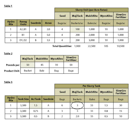
The seed bag is the basic handling unit used in seeding. Before mixing begins, you must determine how much area a bag of seed mix will cover. This will depend on the seeding method. For hydroseeding contracts, the seed bags can be no larger than the area a slurry unit will cover (See Section 10.3.2). For example, if a 1,000 gallon hydroseeder tank covers a quarter acre, then the bags of seed mix would have enough seeds to cover a quarter acre. In this example, the seed mix is divided into four bags per acre (Line L of Figure 10.96). The most typical seed bag coverage is a quarter of an acre because of the increased flexibility, reduced weight, and ease of handling.
The sowing method is an important factor in assembling the seed mix. If the mix is to be used in a seed metering system (Inset 10.19), each seedlot must be thoroughly mixed together to ensure a uniform distribution of seeds of each species on the site. On the other hand, if the seed mix is placed in a hydroseeder, it is not necessary to mix the seeds since all seeds will eventually be mixed in the hydroseeder before application. Other packaging will be required if more than one seedbox is used (e.g., the Truax® seed drill).
Other materials can also be included in the assembly of the seed mix. Mycorrhizal inoculum can be mixed with the seeds, as well as dyes to make seeds easier to see after seeding. Mycorrhizal inoculum and dye will change the rates that seeds will flow. Seed metering systems will have to be calibrated for these materials. Very small-seeded species may need to be sown with carriers, such as rice hulls (Stevens and Munson 2004). For small, fluffy seeds, wheat bran can be added to help prevent them from migrating upward in the seed mix (Dixon and Carr 2001b).
When calibrating seeds for mulch blowing operations, it will be necessary to create more small seed bags that represent smaller calibration areas (Inset 10.20).
10.3.1.7 Determine Seeding Date
The best date to sow varies by site, but typically it is in the fall. On cool, arid sites, seeding later in the fall is better to prevent premature germination prior to the onset of the winter (Monsen and Stevens 2004). On warm, moist sites (e.g., the west side of the Cascade Mountains), sowing can take place in the late summer and early fall, anticipating that seeds will germinate with early fall rains and become established prior to winter. If seeds are sown in the spring or early summer, seed mixes should be composed of species that germinate quickly and do not require a long natural stratification period.
10.3.1.8 Assure Quality
There are several factors to monitor during seeding to assure operations are administered correctly. Depth of seed placement, uniformity in application, target seed densities, and seed handling must be monitored throughout the process. It is important to periodically measure seed depths, especially at the beginning of the operation or when any new site being seeded. Seed dyes are sometimes applied to make seeds more visible. However, these are not useful when seeds are applied through hydraulic seeders or mulch blowers. Uniformity of seed application can be monitored as seeds are being distributed through seed metering or delivery systems. Sometimes seed systems plug or malfunction, resulting in sporadic application of seeds. Poorly applied seeds, where the applicator either misses spots or applies over seeded areas, will also results in an uneven application.
Seed densities can be monitored indirectly by measuring the area where a known weight of seed has been applied and matching it to the estimated acreage it was targeted to cover. For example, on a project where a seed mix is split into a quarter-acre bags, the area seeded with one bag of seed mix would be measured. If a quarter-acre bag covered only 0.2 acres, the seed was sown more thickly and the density was increased by 25% (0.5/0.2). If the seed bag had been applied over 0.30 acre, the seeds would have been spread across more area and the seed density would have decreased by 17% (0.5/0.3). These measurements should be done as each seed mix is being applied. If there is a significant change in density, adjustments to the seeding operations can be made.
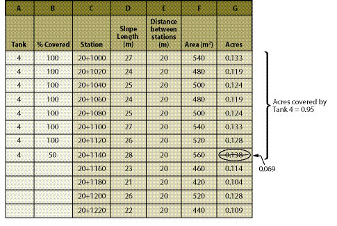
Measuring a seeding area unit is important not only for determining if seeding rates are being applied correctly, but also for accurately paying the seeding contractors. Contract administrators should be measuring the area that each seed bag or known seed quantity is being sown during, or immediately after, seed application. Figure 9.2 in Chapter 9 describes a method to measure area by measuring the slope length that has been seeded at each road station marker and multiplying it by the distance between markers.
Proper seed handling should also be monitored. Seed bags should stored in suitable conditions and always handled with care. Seed bags should not be thrown or dropped or left in unsuitable conditions.
10.3.2 Hydroseeding
10.3.2.1 Introduction
Hydroseeding is a method of hydraulically applying seeds, stabilizers, and soil amendments to the surface of the soil for the primary objective of revegetation. The term hydromulching is often used interchangeably with hydroseeding, but there is an important distinction; hydromulching is the application of hydraulic mulch and surface stabilizers for the primary purpose of erosion control. Hydromulching is typically conducted on multi-year construction projects, when surface soils need to be temporarily stabilized for soil erosion or dust abatement. While hydromulching and hydroseeding operations both must stabilize the soil surface, hydroseeding has the additional and overriding goal of placing viable seeds in a surface environment to germinate and grow into healthy plants. Meeting the dual objectives of erosion control and plant establishment in one operation is often a balancing act. The best methods for soil stabilization are not always optimal for seed germination and plant growth. In this section, we will focus on hydroseeding, not hydromulching. We will discuss how to best meet the needs of early plant establishment using hydraulic sowing methods and leave the discussion of stabilizing the surface through hydromulching to the many articles on this subject and to the manufacturers of these products.
Hydroseeding equipment is composed of: 1) a tank that holds a slurry of water, seeds, soil amendments, and stabilizing products; 2) paddles or agitation jets in the tank to mix the slurry; 3) a high pressure pumping system; and 4) a hose and nozzle (Figure 10.97).
| Figure 10.97 — The hydraulic seeder is composed of a tank that holds and mixes a slurry, and a pump system that moves the slurry through a nozzle for application to the soil surface. |
 |
Tanks come in a variety of sizes, from a few hundred to over 3,000 gallons. As the size of the tank increases, the speed and efficiency of the operation improves. Because the travel time is the same for any size hydroseeding unit, the farther the water source is from the project site, the more efficient larger tanks become.
The hydroseeding tank is analogous to a large mixing bowl filled with various ingredients and blended together with water to make a slurry. Typical hydroseeding ingredients fall into these categories:
- Seed,
- Hydraulic mulch,
- Tackifier,
- Fertilizer,
- Soil amendments, and
- Dye (typically in the hydraulic mulch).
The mixture of ingredients is called a slurry. When a slurry is applied to an acre, it is referred to as a slurry unit. The quantity of each material added to a slurry tank is only limited by the ability of the mixture to be pumped through a hose and shot through a small nozzle without clogging. The tank can only hold so much material before the mixture becomes too thick to pump. Finding the right mix and rates of ingredients is important for efficient use of the equipment. The applicators and manufacturers of these products can recommend optimum product rates.
Hydroseeding ingredients must be thoroughly blended prior to application to achieve uniform seed coverage. There are two types of hydroseeding mixing systems — those that mechanically stir and those that mix using a hydraulic jet. The first system employs rotating paddles to blend the slurry in the tank and a centrifugal pump or positive displacement gear pump for slurry delivery. The second system uses a centrifugal pump to both agitate the slurry and deliver the slurry to the site.
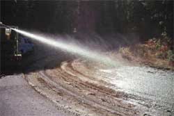
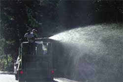
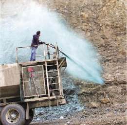
During application, the slurry is pumped to the nozzle for application. The applicator has a choice of nozzles, use of which depends on the site and slurry conditions. Slurry application can be from a "gun" mounted on the top of the hydroseeding unit or from a hose pulled manually to the application site. Stationary application (using a hydroseeding gun) is accomplished where the hydroseeding equipment can easily access the site. These areas are typically cut slopes and fill slopes. Depending on the consistence of the slurry, the pumping system, and wind conditions, slurry can be shot 200 feet or more. Hoses are laid out for sites that cannot be reached this way. Depending on the diameter of the hose and the pumping system, hoses can reach sites over 300 feet from the hydroseeding unit.
Hydroseeding is used when other seeding methods are impractical (See Section 10.3.1, Seeding). Typically, these are steeper sites where ground based seeders are limited. Hydroseeding has the advantage over other seeding methods of applying soil amendments, fertilizers, soil stabilizers, and seeds together in one operation, making this a one pass operation. In addition, seeds that are used in hydroseeding operations do not have to be as clean (that is, free of straw, awns, chaff) as for other seeding methods. This can reduce costs and time associated with seed cleaning operations.
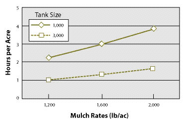
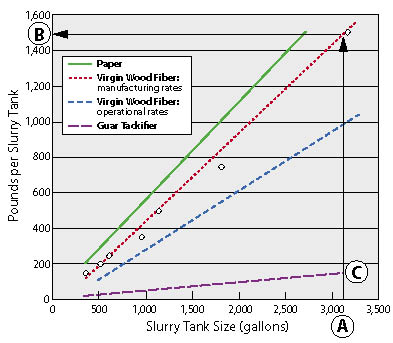
The time it takes to hydroseed is a function of the size of the mixing tank and the amount of hydraulic mulch that is applied on a per acre basis (Figure 10.98). The greater the amount of hydraulic mulch applied per acre, the longer it will take. For example, it takes almost twice as long to apply 2,000 lb/ac of hydraulic mulch through hydroseeding equipment as it does to apply 1,200 lb/ac. For this reason, determining the appropriate amount of hydraulic mulch is important from a cost standpoint. Cost includes not only the costs of purchasing the product, but also the time to apply it. Tank size is also an important factor in application rates; the larger the tank size, the less application time it takes. A 3,000 gallon mixing tank for example, takes less than half the time to cover an acre than a 1,000 gallon tank.
Hydroseeding in wildland revegetation has a number of limitations (Stevens and Monsen 2004):
- Seeds are not placed in the soil
- Seeds and seedlings can dry out
- Some seedlings cannot grow through the hydraulic mulch
- Seeds can be damaged by agitators and pumps
- Precocious germination can occur as a result of moisture in the hydraulic mulch
- Hydroseeding requires large quantities of water
With good planning, implementation, and monitoring, many of these limitations can be managed, resulting in successful revegetation. Ultimately, the success of any hydroseeding project comes down to the availability of water during germination and seedling establishment. Hydroseeding is successful in the landscaping business because seeds are irrigated after hydroseeding until a stand of grass has become established. As one applicator stated, "what people don't understand is you can do the best hydroseeding job in the world but if they don't water it, it's not going to grow" (Brzozowski 2004). The challenge in wildland revegetation is that, for most projects, irrigation is not available. To make hydroseeding successful, strategies must be developed that maintain moisture around the seeds and in the soil during early plant establishment.
10.3.2.2 Integrate Hydroseeding into Revegetation Strategy
From a revegetation standpoint, hydroseeding serves as: 1) a method of seed placement, 2) a means of stabilizing the soil surface for controlling erosion and to allow seedlings to become established, and 3) a way to apply fertilizers and other soil amendments. These objectives cannot always be met in one hydroseeding operation. It often requires that each objective be considered independently, and then integrated into an overall strategy. Clarifying objectives, based on the site specific conditions of the project, and determining the best way to achieve them using hydroseeding equipment as part of the approach, will lead to the best revegetation results. For example, seed placement and fertilizing are different objectives, yet meeting both objectives is often accomplished in one hydroseeding operation out of convenience. However, the best time to apply fertilizers on many projects is after the seeds have germinated (See Section 10.1.1). Instead of meeting fertilizer and seeding objectives in one hydroseeding operation, separating them into two different applications would be a better strategy for meeting overall project objectives.
On a site with high surface rock, for example, the main objective would be seed placement. Little importance would be placed on surface stabilization since the rock has already created a stable surface. The best potential sites for seedling germination on this harsh surface would be between the surface coarse fragments, where seeds are protected and moisture collects. Yet a common mistake that occurs in many hydroseeding projects is to include the same rates of tackifiers as would be used on a soil surface. Under these circumstances, tackifiers adhere seeds to the rock surface, preventing the seeds from washing between the gravel and cobbles that cover the surface. The objective of stabilizing the surface is not only unnecessary in this example, it would negatively affect placement of seeds.
Hydroseeding should always be accomplished within a strategy of creating an optimum seed environment. The hydroseeding operation places seeds on the surface of the soil which is often a poor environment for germination. Hydraulic mulch is inferior to long-fiber mulches in reducing surface temperatures, maintaining soil moisture, and moderating surface temperatures (See Section 10.1.3). The term "hydraulic mulch" is misleading because most materials that fall into this category lack many of the important properties associated with mulches (See Section 10.3.2.5). By their nature, hydraulic mulches are more like a growing medium than mulches because of their capacity to absorb water (Most hydraulic mulches hold greater than 1,000 times their weight in water).As a growing medium, hydraulic mulch maintains high moisture around the germinating seeds. But once the hydraulic mulch dries out, which is often very quickly on dry sites, it no longer protects the seeds from drying as a mulch would and germination rates are compromised.
The literature is scant and inconclusive on the benefits of hydraulic mulch to seed germination and seedling establishment in wildland conditions. Carr and Ballard (1980) found no difference in plant establishment when seeds were applied with and without hydraulic mulches, but only low rates of hydromulches were compared. One approach to increasing seed germination that is often used in drying climates is a two pass application system, where seeds and a minimum amount of hydraulic mulch are applied in the first pass, then covered by a thick application of hydraulic mulch in a second pass. While this application method appears to have some advantage over a one pass operation because the seeds are covered with a greater thickness of hydraulic mulch, it is not known what the difference in germination and seedling establishment rates might be. The benefits from a germination standpoint are probably not seen until the hydromulch rates are high (3,000 lb/ac or greater). Even then, on arid sites receiving less than 6 inches precipitation, higher hydraulic mulch rates can intercept the low amount of precipitation that is received, preventing moisture from reaching the seeds (See Section 5.2.2). Since it is uncertain whether hydraulic mulches improve germination, it is better to base mulch rates on surface stability objectives than on seeding objectives and use other methods to improve seed germination. For example, it might be more effective to reduce the amount of hydraulic mulch to the minimum amount necessary to apply seeds and, with the costs savings, apply a long-fibered mulch in a second operation.
10.3.2.3 Identify Hydroseeding Areas
Hydroseeding should take place after the final slope shaping and topsoil placement have been completed. Several months before hydroseeding is to take place, the site must be visited to finalize an implementation plan that includes the locations of where the plants or cuttings are to be installed and where seeding will take place. While most of the hydroseeding areas will conform to the revegetation units developed during planning, things always look different after construction. In this field review, the exact locations of the areas that will be hydroseeded are drawn on a road map and areas are identified where different seed mixes, fertilizer types/rates, or hydraulic mulch rates will be applied.
The acreage for each hydroseeding area is calculated using methods described in Figure 9.2 in Chapter 9. This method partitions the cuts lopes and fill slopes into rectilinear units by road stations and calculates acreage between each unit. This information is then summarized in a hydroseeding table (shown in Figure 10.107) that is used to develop task orders. It can also be used in the field for keeping record of acreages and location of hydroseeding operations.
The proximity to streams must be considered when locating hydroseeding areas. If hydroseeding areas are adjacent to ditches or waterways that drain into live streams, a buffer should be included around these features to avoid entry of fertilizers into the stream system. Fertilizers applied to these sites have the potential of entering the ditches during rainstorms and eventually reach a stream course as nutrient pollution. Road runoff can be a significant contributor of nutrients to water systems (Reuter and others 1998).
10.3.2.4 Determine Seeding Rates
Sowing rates for hydroseeding are calculated using the same method outlined in Figure 10.96 in Section 10.3.1. The reader is referred to this section for determining seeding rates for any type of sowing method. These sowing calculations assume that the method of sowing does not cause damage to seeds. This might not be a good assumption with hydroseeding, which has been shown to increase the risk of seed breakage in the hydraulic seeder tank during mixing (Kay and others 1977; Wolf and others 1984; Pill and Nesnow 1999). Additions of fertilizers further increase the risk by exposing seeds to high salt levels when seeds are in the slurry tank and also after they are applied to the soil surface (Brooks and Blaser 1964; Carr and Ballard 1979; Brown and others 1983). Taking precautions to reduce the risk of seed damage during hydroseeding will increase the seed germination rates and reduce the amount of seed needed for the project.
Considerations that can reduce the risk of damaging seeds include:
- Type of hydraulic seeder,
- Seed condition,
- Duration in slurry,
- Seed moisture,
- Hydraulic mulch,
- Nozzle and nozzle position, and
- Fertilizers.
Hydraulic Seeders — Hydraulic seeders that use centrifugal pumps for agitation and delivery can have a higher potential to damage seeds than systems with paddles and rubber-coated gear pumps (Kay 1972a; Kay and others 1977). Kay (1972a) found that germination of intermediate wheatgrass (Agropyron trichophorum [Link Richt.]) seeds was reduced from 80% (control) to 10% germination after one hour in a centrifugal agitation system; after two hours, germination was reduced to 1%. There was no reduction in germination after one hour using paddle agitation, but germination declined to 59% after two hours. Pill and Nesnow (1999), however, found that centrifugal pumps did not reduce germination rates of Kentucky bluegrass (Poa pratensis) and perennial ryegrass (Lolium perenne) after mixing for an hour in a slurry tank.
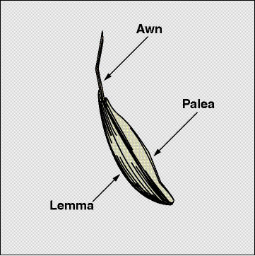
Seed Condition — Grass seeds are enclosed by sets of bracts, called the lemma and palea. These structures provide a protective covering (Figure 10.99) and are believed to reduce seed breakage during hydroseeding agitation and application. In the aforementioned study, Pill and Nesnow (1999) believed that one of the primary reasons there was no decline in germination after an hour of mixing in a slurry tank was because the lemmas and paleas were still intact around the seeds. The association between presence of these seed structures and protection from seed breakage during hydroseeding should be considered when cleaning seeds for hydroseeding. Seed cleaning is necessary for storage and seeding (See Section 10.2.1 and Section 10.2.4). However, seeds for use in hydroseeding operations do not have to be as clean as seeds used in other seeding methods. Each species has different cleaning requirements for hydroseeding. Some require thorough cleaning, while others might require very little cleaning. It would be beneficial to discuss the level of seed cleaning for hydroseeding with your seed extractory personnel and seed increase contractors.
Duration in Slurry — The longer seeds are mixed in the slurry tank, the greater the potential for breakage. Kay and others (1977) found that after 20 minutes of agitation, seed germination decreased significantly (Figure 10.100). For this reason, it is important to add seeds immediately before application.
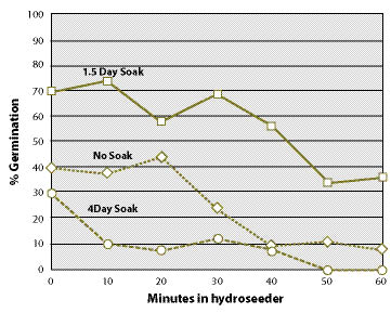
Seed Moisture — As a general rule, moistened seeds have less potential for breakage than dry seeds because they are more flexible when impacted. Kay and others (1977) found that soaking seeds for 1.5 days prior to application significantly increased germination over dry seeds (Figure 10.100). Longer soaking periods (4 days) had negative effects on germination because radicals were emerging and were damaged with mixing.
Soaking seeds prior to hydroseeding will unfortunately initiate seed germination, which is not usually desirable for hydroseeding projects. Pill and Nesnow (1999) suggest seed priming as an alternative to soaking. Priming is a seed treatment that partially moistens seeds without initiating seed germination (Pill and others 1997). Seed is mixed at one part seed to 10 parts moist vermiculite (although peat could be used as a substitute) and stored at cool temperatures for up to 10 days prior to hydroseeding.
Hydraulic Mulch — Hydroseeding without hydraulic mulch can increase seed damage (Kay 1972a, 1978). Using a minimum rate of 500 lb/ac hydraulic mulch is suggested for protecting seeds (Kay 1978).
| Figure 10.101 — Incorporating 10-30-10 fertilizer into hydroseed slurries can reduce the germination of some species (Carr and Ballard 1979). |
 |
Nozzle Type and Nozzle Position — Shooting slurry straight at the soil in close range can damage seeds. The impact at high speeds can cause seed coats to break. As one hydroseeding operator describes the action, "we just shove that seed right smack in the ground with a lot of force ... the gun was slamming straight to it" (Brzozowski 2003). Describing this action to a Forest Service seed extractory specialist, his reaction was, "that can't be good for the seed" (Barnar 2007). In the seed production and seed extraction businesses, handling seeds carefully is a high priority. This attitude and practice should not stop with the seed producers, but follow through to the application of seeds. One application practice that could reduce seed damage is to aim nozzles so the slurry is not hitting the soil surface with full force at close range. Arching the slurry stream so the spray hits with lower force is more desirable. Using less pressure or lower pressure nozzles, such as fan nozzles, can also reduce seed damage (Figure 10.102). Some soils are very loose or powdery after construction, which can cushion the seeds, as opposed to very compacted surfaces. Seeds applied to these surfaces can be buried under the loose soil when the slurry is shot straight at the surface, offsetting the effects of seed breakage and increasing germination potential (Mast 2007).
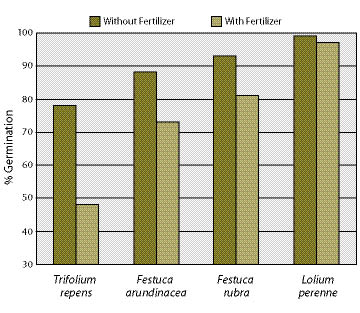
Fertilizers — Adding fertilizer to the slurry can reduce germination of certain species due to the effects of fertilizer salts on seed imbibition, or uptake of water (Brooks and Blaser 1964; Carr and Ballard 1979; Brown and others 1983). This is not just a problem when seeds and fertilizers are mixed together in the slurry tank; it can also negatively impact the seeds after they are applied to the soil surface and before the first rains dilute the surrounding salts. Effects of fertilizer salts will be more detrimental on sites with low rainfall. Carr and Ballard (1979) found white clover (Trifolium repens) and, to a lesser degree, Festuca spp. had the greatest reduction in germination. They suggest white clover should be applied by hand, separate from the hydroseeding operation.
Assuming that most native seeds, especially legume species, are affected by fertilizer salts, it is important to understand what the effects of different types and rates of fertilizers will have on the salt concentrations in the slurry. Brooks and Blaser (1964), Carr and Ballard (1979) and Brown and others (1983) used inorganic, fast release fertilizers, which dissolve quickly in solution (See Section 10.1.1). Organic and control release fertilizers, on the other hand, dissolve slowly and therefore should have lower salt levels in solution. Whichever fertilizers or rates are used, testing the slurry for soluble salts should be conducted to assure that concentrations are not lethal (See Section 5.5.5).
The effect of hydroseeding operations on seed viability is an important issue and deserves more research attention. Monitoring information can be used to broaden our understanding on how to properly use this important tool.
10.3.2.5 Select Hydraulic Mulch and Determine Rates
Hydraulic mulch is a low bulk density material applied through a hydraulic seeder to increase surface soil strength and reduce erosion. At high application rates, seeds are covered, thereby increasing the potential for increased seed germination. Commercial hydraulic mulches are derived from wood fiber, recycled paper (wood cellulose), sterilized grass straw, or a combination of the three. Wood fiber mulches are manufactured from wood chips thermally treated by a steam and high pressure shredding process; wood cellulose mulches are made from waste paper materials such as recycled newspaper and cardboard (Trotti 2000). Hydraulic mulches typically have very high water-holding capacities (over a 1,000 times their weight in water). A pound of wood fiber mulch, for instance, absorbs between 1.5 to 2.5 gallons of water and, inversely, a gallon of water holds between 0.40 and 0.66 lb hydraulic mulch. This is important information to know when determining how much hydraulic mulch to add to a slurry tank. Most operators will not exceed a ratio of 0.4 to assure they do not clog their system with a slurry that is too thick. At this proportion, a 1,000 gallon tank would hold 400 pounds of wood fiber mulch. Product specification sheets should indicate the ratio of hydraulic mulch to water for hydroseeding equipment.
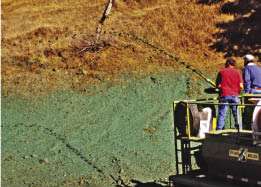
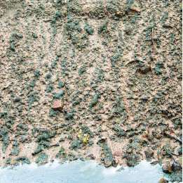
The depth and cover of hydraulic mulch depends primarily on the quantity and properties of the mulch placed in the tank. Typical hydroseeding projects range in application rates from 500 to 3,000 lb/ac. At low application rates (<1,000 lb/ac), wood fiber mulch will not cover the entire soil surface, leaving most seeds and much of the soil surface exposed. At high rates (>3,000 lb/ac) the soil surface and seeds are usually completely covered (Figure 10.103). With the appropriate mix of tackifiers, hydraulic mulch rates above 3,000 lb/ac can bond together to form a continuous sheet, called a bonded fiber matrix, or BFM. A bonded fiber matrix will stabilize seeds and control surface erosion up to a year after application.
The length of the wood or cellulose fibers is an important characteristic in creating a soil cover mulch that does not restrict seed germination or plant growth. Cellulose mulches have shorter fibers than wood fiber mulches and, because of this, these materials compact much easier when they are applied. Applying too much cellulose mulch can result in a soil surface that has the consistency of "paper mache." At application rates greater than 1,500 lb/ac cellulose mulch, there is a reduction in infiltration and air exchange, and seed germination and seedling establishment are decreased (Gassman 2001). Some manufacturers have overcome this problem by mixing straw, a long-fibered material, with paper mulch. Typically, cellulose mulch requires 20% to 40% more material to achieve the same uniformity of coverage as wood fiber mulch (Trotti 2000) (Figure 10.104). While recycled paper mulches are typically less expensive than wood fiber, the cost savings are partially offset by the increased amount of paper mulch used. Blended mulches (those with equal portions of wood fiber with recycled paper) are an effort to improve the characteristics of recycled paper by adding wood fiber.
The use of hydraulic mulch for seed germination becomes less important on wetter sites, especially in climates where there is little soil drying during germination (Carr and Ballard 1980). These conditions are found from fall through early spring on many sites in the Coast Range and Cascade Mountains, and microsites that include north aspects and sites shaded by vegetation. On these sites, 1,000 lb/ac or less might be sufficient for seed germination. In areas with high rainfall and erosive soils, higher hydraulic mulch rates or even a bonded fiber matrix might be needed to keep seeds and soil in place until seeds have germinated and grown into established seedlings.
10.3.2.6 Select Tackifier
Tackifiers are sticking agents that bind soil particles together and protect the surface from wind and water erosion. When applied with hydraulic mulch, tackifiers increase the effectiveness of the mulch as a soil cover by binding the hydraulic mulch fibers and the surface soil particles together. Tackifiers create water-stable surfaces, which means they are capable of repeated wetting and drying and do not lose strength after a series of rainstorms. Hydraulic mulch and tackifiers can remain effective even through a winter with high precipitation (Figure 10.105).
Selecting a tackifier can be difficult. There are numerous commercially available products on the market from which to choose. Unless you have used these products side by side in the field, it is difficult to know the difference. A hydraulic seeder operator can offer advice on tackifiers and other hydraulic seeding products, since they have tried a variety of products and would usually have a good idea of effectiveness.
There are two general types of tackifiers commonly used in hydroseeding — organic and synthetic. Organic tackifiers are derived from plant materials which include guar, plantago, and other plant starches. Synthetic tackifiers are manufactured polymers and copolymers that include polyacrylamides (referred to as PAM), acrylic polymers and copolymers, methacrylates and acrylates, and hydro-colloid polymers. Organic tackifiers break down biologically and are typically effective for at least three months, depending on site conditions and product type. Synthetic tackifiers are photo and chemically degradable and have somewhat greater longevity than organic tackifiers, lasting up to a year on many sites (CASQA 2003b).
Revegetation specialists and operators usually develop a preference for tackifier products based on: 1) ease of handling and storage, 2) ease of application, 3) toxicity to plants, 4) environmental concerns, 5) weather restrictions, and 6) application rates.
Handling and Storage — Tackifiers are available as dry powder or liquid formulations. Most organic and some synthetic tackifiers are packaged as dry powders. These products are easy to handle and store because they weigh less and have less bulk than liquid containers. Liquid tackifiers must be stored in areas that will not freeze if stored over the winter. Handling and disposal of plastic containers is also a consideration when using liquid tackifiers.
Ease of Application — An important property of tackifiers is viscosity. Viscosity is the measure of the "stickiness" of a tackifier, or the propensity of the tackifier to hold a slurry together when it is applied. Tackifiers with high viscosity, such as guar based tackifiers, will hold the slurry together as a fine stream when pumped from the nozzle (Figure 10.106A), and the stream of slurry will shoot farther. When a slurry with high viscosity hits the soil surface, it sticks and does not easily run off. A slurry with low viscosity, on the other hand, will separate as it is comes out of the nozzle and drift, especially if there is a breeze, resulting in uneven application (Figure 10.106B). If low viscosity slurries are applied at rates that are greater than the soil infiltration rates, the slurry will run off the surface. Not only will seeds be lost, but other materials in the slurry (including fertilizers) have the possibility of moving into surface drainage systems (Figure 10.106C).
Tackifiers act as lubricants and create less friction through the hydraulic equipment. With high viscosity tackifiers, equipment runs smoother and nozzles do not plug as frequently. This will enhance the overall performance and longevity of the equipment.
Toxicity to Plants — One reason organic tackifiers are sometimes preferred over synthetic tackifiers is the belief that these materials are better for seed germination and seedling establishment. They are organic substances that break down into non-toxic compounds. While organic tackifiers are sometimes advertised as being better for plant health, there is nothing in the scientific literature to indicate that synthetic tackifiers are any more harmful or toxic to plant establishment than organic tackifiers.
Environmental Concerns — There have been concerns about the use of polyacrylamides (PAM) on human health and the environment. Acrylamide, a known neurotoxin to humans, is the main ingredient of this polymer. Polyacrylamides alone have low toxicity — LD50 of 5,000/kg oral dosage (Peterson 2002). However, in the manufacturing of the polymer, some acrylamide is formed. The US Food and Drug Administration has set a maximum allowable acrylamide content in PAM of 0.05%. While PAM does not appear to break down in the environment to acrylamide, if released during decomposition, it is thought to be quickly decomposed by soil microbes (Peterson 2002). Furthermore, since PAM degrades slowly in the environment, there should not be an accumulation of acrylamide in the soil (Claassen and Hogan 1998). Evans (2006) cites reviews by Barvenic (1994) on health hazards and Goodrich and others (1991) on aquatic macrofauna, edaphic microorganisms, or crop species. When polyacrylamides were applied at recommended rates, the materials were found to be safe for the environment. The reader is referred to Barvenik (1994) for a comprehensive discussion of PAM in the environment.
As with all products used in revegetation, a material safety data sheet should be requested from the manufacturer of the product and reviewed for possible human effects and effects to the environment. Some states have regulations on the use synthetic polymers in landscaping. It is important to be abreast of the latest environmental regulations (Peterson 2002).
Weather Conditions — Tackifiers have limitations and conditions for proper application, including: soils must be moistened prior to application; there must be a 1- to 3-day drying period after application; the site cannot freeze during or immediately after application; or they must be applied between a certain temperature range. It is important to understand which environmental restrictions apply to the tackifier you are using and how it might affect the hydroseeding operations. A site that is expected to be wet in the fall, for instance, will require a tackifier that needs a minimal curing period.
Tackifier Rates — When tackifiers are used with hydraulic mulches, tackifiers are applied at rates at 5% to 10% of the weight of the hydraulic mulch (CASQA 2003a). Refer to manufacturer labels for specific rates.
10.3.2.7 Select Other Slurry Components
The remaining components of the hydroseeding slurry can include dyes, fertilizers, biostimulants, and mycorrhizae.
Dyes — Dyes are used as markers for the applicator to indicate where the slurry has been applied. Most hydraulic mulches include dyes, so it is not usually necessary to include dyes in the slurry when using these mulches.
Fertilizers — Fertilizers are often applied through hydroseeders. Determining the type and amount of fertilizers to use is discussed in Section 10.1.1.
Biostimulants — Biostimulants are sometimes applied to the slurry.
Mycorrhizae — Mycorrhizae are often included in the slurry (See Section 10.1.7, Beneficial Soil Microorganisms).
10.3.2.8 Locate Water Source
It should go without saying that you cannot hydroseed without a water source, yet a common mistake is to wait until the last minute to locate a source. For many parts of the western United States, water sources can be long distances from the project site. It is important to establish early where water will be obtained for hydroseeding early in the planning process.
Considerations when selecting a water source include:
Distance — On projects where the water source is a long distance from the hydroseeding site, large slurry tanks will increase the efficiency of the operation. Conservation of water should be a priority in these circumstances. Covering more area with each slurry tank is one way to reduce water needs. This can be accomplished by applying lower rates of hydraulic mulch and tackifier per acre.
Water Quality — The quality of the water for hydroseeding must be low in salts and other potentially toxic compounds. If in doubt, send a sample to a water quality lab for testing or, at minimum, run pH and conductivity measurements on a sample.
Water Use Permits — Always check with the agency or landowner for permits to use their water.
10.3.2.9 Develop Hydroseeding Contract
Once a basic hydroseeding plan is developed, a contract is developed. The contract usually contains most of the following elements:
Site Location and Description — A general description of the site, slope gradients, location, and time of year the hydroseeding will occur should be addressed.
Products and Rates — The hydroseeding products or equivalent products (hydraulic mulch, tackifiers, fertilizers, and so on) are identified, and the rates per acre for each product are stated for each hydroseeding mix or mixes. The total number of acres for each hydroseeding mix must be tabulated.
Water Source — The location and distance to each water source are described. The contract should indicate whether it is the responsibility of the contractor to obtain agreements from owners for use or any required water permits.
Storage Area — The contractor will want a site to store hydraulic mulches, tackifiers, fertilizers, and other materials associated with the hydroseeding operation. The site should be in close proximity to the hydroseeding areas and relatively safe from vandalism.
Equipment — If specific types of hydraulic seeders are required for the job, they should be specified in the contract. Using hoses to access portions of the project site will often be necessary. The contract should specify how many feet of hose are needed and what percentage of the project will be applied by hose.
Cleaning Equipment — The contract must state that the tank and hoses will be cleaned from all previous hydroseeding or hydromulching projects. The equipment will be inspected and, if it does not pass inspection, the contractor will be required to clean equipment at an approved offsite location.
Weather Conditions — The weather conditions, based on manufacturer specifications, should be stated. The contract should specify acceptable temperature ranges and wind velocities. It should also state whether rain or freezing temperatures can occur within a specified period after application. A provision should be stated that applications will not occur on frozen ground. Some tackifiers also require that the soils be moistened before application.
Mixing — The contract should state that the seeds be mixed into the slurry immediately before application. It should further state that the slurry must be applied within 30 minutes after the seeds have been placed in the tank. When the seeds are in the slurry, it should be moderately agitated only enough to mix the seeds and keep the slurry from separating.
Application — The slurry should be applied at a rate that covers 85% of the soil surface. Slurry should not run off the soil. If it does, adjustments to application speeds or nozzles must be made. Figure 10.102 shows the spray pattern of two types of nozzles. Avoid applying slurry at a range that causes slurry to splash off the surface and soil to dislodge. A two pass method is preferred to obtain good seed coverage. In the first pass, 50% or less of the slurry is applied, followed by the second pass that applies the remainder of the material. Each pass is applied in a different direction (bidirectionally), which reduces the "shadow effect" created by just one pass and may serve to better lock the matrix together (Bill Mast personal communication).
Traffic Control — The contract must state how traffic safety will be ensured during application. Will the contractor be required to supply signs, warning lights, or flaggers?
10.3.2.10 Keep Good Records
Hydroseeding is a complex task. Not only are several products being applied at different rates at one time, but they must be evenly applied over large complex areas. A skilled hydroseeding operator must be at the helm, and you must keep track of what is being applied and the acres on which it is being applied. This will assure that you are getting the target amount and enable accurate payment to the contractor.
The records begin with the original hydroseeding prescription. These are the planned application rates of each hydroseeding material. It is not enough to know what you want as a finished product on the site; you must understand how it will be accomplished. This means that you must translate the prescribed product quantities per acre into how it will actually be applied. These calculations can be challenging, especially when the hydroseeding operation is in full swing. It is better to have some idea how this will work before you arrive in the field. Inset 10.21 is a guide through a process of determining how much of each hydroseeding material must go into a slurry tank. These calculations, along with the contract specification, become the operation plans.
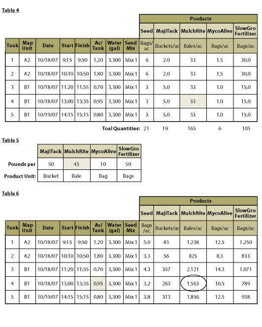
During the hydroseeding operations, the contract inspector must keep track of each slurry tank that is applied. This includes the time, amount of water, quantities of products, location, acreage, and weather conditions. Calculating the acreage of each slurry tank is important in the field to assure that the rates of materials are being applied as prescribed. This can be accomplished using a method shown in Inset 10.21, Table 4. When this information is collected, the actual applied rates of materials per acre can be made using methods shown in Inset 10.21, Table 6. This will tell you how close each slurry tank came to the prescribed rates. This is important feedback for the hydroseeder operator. If the application rates were off significantly, adjustments can be made quickly. These records can be summarized at the end of the project to determine total quantity of materials used and the number of acres covered. This information can be the basis for contract payment.
10.3.3 Installing Cuttings
10.3.3.1 Introduction
Live cuttings have a variety of uses in revegetation projects, from stream restoration to roadside stabilization. When live cuttings are used as slope reinforcement, barriers to soil movement, or integrated into retaining structures such as rock gabions, crib walls, or rock walls, they form the living component of a soil biotechnical engineering system (Sotir and Gray 1992). In slope reinforcement, live cuttings initially play a structural role by increasing soil strength and preventing surface erosion. As cuttings establish into plants, soils are stabilized through a dense network of interlocking root systems. Soils are further stabilized during the growing season as soils dry due to increased evapotranspiration and rainfall interception.
Soil biotechnical engineering techniques are well documented. Gray and Leister (1982), Sotir and Gray (1992), and Lewis (2000) are excellent sources on road and slope stabilization, and the reader should refer to Bentrup and Hoag (1998) for streamside stabilization. Section 10.2.2 discussed how to collect and evaluate live cutting quality; this section will focus on the care and installation of live cuttings to optimize the success of biotechnical engineering and other roadside revegetation projects. For simplicity, live cuttings are grouped by general application in biotechnical engineering projects: 1) live stakes, 2) live brush layers, and 3) live fascines.
10.3.3.2 Live Stakes
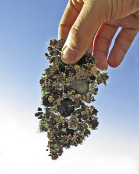
Live stakes are individual cuttings that are inserted into the slope to physically stabilize the soil and, with time, grow into individual plants with dense, interconnecting roots that further increase soil stability. Live stakes are used to repair small earth slips and slumps (Sotir and Gray 1992) and as pole plantings for stabilizing streambanks (Bentrup and Hoag 1998). Joint planting refers to live stakes inserted into voids or openings between large rocks. The live stakes can take root and revegetate rock riprap sites or portions of fractured bedrock (Sotir and Gray 1992). Live stakes are also used in live fascine installations and to anchor erosion mats to the soil (Lewis 2000). In gullies, draws, or intermittent streams, live stakes are placed in rows as live silt fences (Polster 1997) to slow water velocities and catch sediments and other debris. In saturated soil conditions, where excavation for brush layering or fascines is not feasible, live stakes can be densely stuck by hand.
Collection — Live stakes are collected from the main stems of donor plants located in the wild (See Section 10.2.2) or from stooling beds in nurseries (See Section 10.2.5). The optimum period to collect cuttings is during the dormant period, after the plants have lost their leaves. If cuttings are collected outside this period, testing the viability of the cutting material is essential (See Section 10.2.2.4). It is important to collect cuttings with several dormant buds because this is where shoots will originate (Figure 10.108).
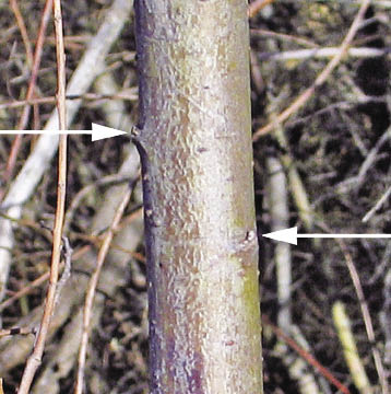
When preparing stakes, all side branches are removed, leaving just the stem. Only stems with diameters between 1 and 3 inches are used. Stems are cut into lengths of 1 to 3 feet, depending on how the materials will be used. It is important to select the appropriate cutting length. Stems that are too short will affect the success of the project, and cuttings that are too long will increase the costs of the project. During collection, basal ends of the cuttings are always oriented in the same direction to assure that the buds will be aligned. This will help avoid confusion later when the stakes are being installed. Finding the orientation of the buds is often difficult (Figure 10.108) and having to reorient in the field takes time. As individual stakes are made, the top of the stake is cut flat, while the basal end is cut at an angle (Figure 10.109). This makes the stake easier to insert into the soil and orients the live stake so the buds are facing up and away from the soil surface. If buds are facing down, the live stake will not root.
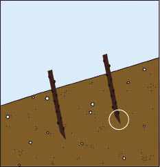
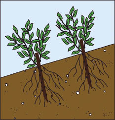
During collection, live stakes are wrapped in small bundles with twine. The size of the bundle must be light enough to be easily carried. Once the bundle size has been determined, the numbers should not vary in order to track cutting quantities. Stakes should be cut from healthy donor plants. Stems that have obvious insect or disease damage should not be used. It is often easy to forget that live cuttings are plant materials, like seeds and seedlings, and must be handled and stored with care.
Storage — It is recommended that live, dormant stakes be collected and installed the same day (Sotir and Gray 1992; Lewis 2000). This is not always possible in a road construction project. When it is not, temporary storage in Forest Service district tree coolers is an option. Temperatures in these facilities should be set below 40°F and, if humidifying equipment is available, it should be kept on high. For longer-term storage (over two weeks), cuttings should be wrapped in plastic or moist burlap to prevent the vegetative material from drying out and temperatures should be set just below freezing. Lower temperatures can result in damage and even death (Wearstler 2004). As a last resort, cuttings can be temporarily stored outside, provided: 1) daily temperatures are low (<50 °F) and humidity is high, 2) cuttings are completely wrapped in plastic, 3) temperatures will not drop below 25 °F, and 4) the site is shaded from the sun.
Preparation — Studies of black willow (Salix nigra) have shown that soaking dormant cuttings prior to installation can increase survival (Schaff and others 2002; Martin and others 2005; Pezeshki and others 2005; Pezeshki and Shields 2006). Soaking for approximately 10 days appears to be the optimum period for black willow (Schaff and others 2002; Pezeshki and Shields 2006). Soaking non-dormant cuttings, however, appears to be detrimental to survival (Pezeshki and others 2005; Pezeshki and Shields 2006). Species native to the western United States might respond similarly to the black willow. The effects of soaking can be tested in other willow species using a method outlined in Section 10.2.2.4. If live stakes are soaked in streams, it is important to be sure they are sufficiently protected from being swept downstream during high precipitation or snowmelt.
Installation — For most applications, live stakes are installed perpendicular to the soil surface. When installed, no more than one quarter to one fifth of the cutting is exposed (Sotir and Gray 1992; Darris and Williams 2001). Buds are always pointing up and away from the soil surface with at least two healthy buds above the soil surface. It is essential that soil be firmly packed around live stakes so there are no large air spaces surrounding the cutting. Live stakes can be installed using techniques described in Section 10.3.4, Installing Plants. These include a shovel, auger, or expandable stinger. In addition to these methods, several techniques are available specifically for live stake installation, which include a hammer, stinger, or waterjet stinger.
Hammer or Mallet. Live stakes can be pounded into the ground using a hammer or mallet. The angled basal end of the stake is placed on the soil surface and the top of the cutting is struck. A small two by four wood block can be placed on the top to absorb the impacts and reduce the risk of splintering the stake. If splintering does occur, the splintered ends should be cut (Lewis 2000). After cutting, there must still be several viable buds above the soil surface. Using a hammer or mallet works best when soils are loose and low in rock fragments. It becomes more and more difficult as rock content or compaction increases. Smaller stem diameters are often not sturdy enough for this installation method.
Stinger. The stinger is a good method for installing live stakes on rocky or compacted soils. A pilot hole is created by mechanically pushing a metal rod into the soil. A live stake is inserted into the hole and tamped to the bottom using a hammer or mallet, as discussed above. Some operators will create the hole with the stinger and, after placement of the stake, use the face of the excavator or backhoe bucket to push the stake further into the soil. The hole created by the stinger is often larger than the diameter of the stake, and the soil must be tamped in around the cutting to reduce air space and create good soil contact. A stinger can be made by welding a long piece of rebar to the bucket of an excavator or backhoe. The stinger is limited by slope gradient and terrain accessibility.
Waterjet Stinger. The Waterjet Stinger hydraulically creates a hole for installing live stakes. A pump draws water from a stream, lake, or water truck for delivery through a hose to the stinger nozzle. As the tip of the nozzle is pushed into the ground, high-pressure water is injected into the soil, creating a slurry (Figure 10.110). When the Waterjet Stinger is removed, a stake is quickly pushed into the resulting slurry at the desired depth. As water drains from the slurry, soil settles around the cutting, resulting in good soil contact.
| Figure 10.110 — The Waterjet Stinger (A) injects high-pressure water into the soil, turning it to a slurry (B) into which a live stake can be inserted (Photos courtesy of Chris Hoag). | |
|
A.
|
B.
|
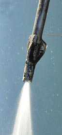
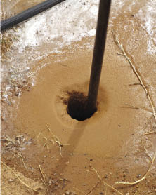
The advantages of using the Waterjet Stinger are: 1) it is simple to operate and transport; 2) little training is necessary; 3) production rates are high; 4) holes are deep, assuring that cuttings are planted directly into a wet environment, 5) soils are saturated around the cutting for a long period of time; and 6) the soil slurry settles around the cutting, eliminating air pockets in the rooting zone (Hoag and others 2001). The disadvantage of the Waterjet Stinger is that it requires a source of water. If the project is not near a body of water, it can be brought in using a water truck or large water storage containers placed in the back of a truck (Figure 10.111). The Waterjet Stinger is also limited by the amount of rock present in the soil. This equipment does not work well in soils containing gravels, cobbles, and boulders that obstruct the downward movement of the probe (Hoag 2007). Sandy soils drain quickly, so installation of cuttings with the Waterjet Stinger must be done quickly and with a little more effort. Steep slope gradients and rough terrain also limit equipment and the transportation of water. For more information on the Waterjet Stinger refer to Hoag and others (2001).
| Figure 10.111 — A 250-gallon water tank with pump can be installed in the bed of a pickup truck to supply water for Waterjet Stinger sticking. |
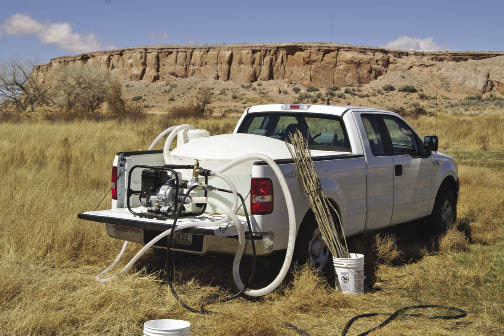 |
Expandable Stinger. The expandable stinger can install live stakes into all soil types and soil conditions, from rocky to compacted. It can plant long cuttings (> 4 ft), and stems of most diameters (including very small diameters). The stake is placed into the stinger, which is inserted into the soil and released, leaving the cutting at the desired depth (See Section 10.3.4.3, Select Planting Tools and Methods). This installation method can leave large air spaces around cuttings. It is therefore recommended that soils be tamped around the cutting after placement.
Hand-Sticking. Hand-sticking is appropriate in areas where soils are mucky or saturated, including recent landslides and wetlands, and cuttings can easily be inserted into the soil. Because this installation method can be done quickly, areas can be planted at very high densities (Figure 10.112).
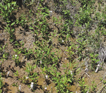
10.3.3.3 Live Brush Layers
Live brush layers are cuttings that are spread on excavated benches and covered by soil (Figure 10.113). This practice is used in several biotechnical engineering applications, including brush layers and modified brush layers. Constructing brush layers is a three-step process in which contour benches are excavated, live branches are spread across the bench surface, and branches are covered with soil from constructed benches directly upslope. The process begins at the bottom of the slope and is repeated until the entire slope is installed with brush layers. In a modified brush layer system, the brush layers are resting on, and supported by, logs or live fascines (Sloan 2001).
| Figure 10.113 — Live brush layers are cuttings that are placed on benches and covered with soil (A). The basal end of the cuttings should extend back to the base of the bench, and the growing tip should just show out of the soil. When placed on the contour and at regular intervals, live brush layers form a network of roots and vegetation that tie the slope together in a series of strips, increasing slope stability and reducing erosion. | |
|
A.
|
B.
|
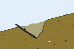
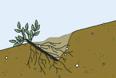
Brush layers and modified brush layers increase slope stability and reduce erosion by breaking slope length, reinforcing soil, trapping sediment, increasing infiltration, acting as horizontal drains, and reinforcing soil as cuttings develop roots (Sotir and Gray 1992). Live brush layers can also be used to vegetate crib walls, rock gabions, and rock walls. In this application, live branches are placed on benches that are created as these structures are built. For crib walls (Inset 10.22), live layers are placed on the bench created behind each layer of logs; in rock gabions, live layers are placed on each layer of gabion baskets.
|
Inset 10.22 — When Should Seedlings or Rooted Cuttings be Substituted for Live Cuttings? Live cuttings are widely used in biotechnical engineering projects. Sometimes, however, it is more practical to substitute rooted cuttings or seedlings in place of live cuttings. This is especially the case when the road project calls for cuttings to be planted in the summer or fall, when dormant, live cuttings are not available, or when live cutting material is not available in large enough quantities. For example, a road near a wild and scenic river is being widened. Biotechnical engineering techniques using live willow cuttings are being planned for retaining walls to increase slope stability in areas adjacent to the river. The design looks good on paper (A). However when discussing the details with a revegetation specialist, question arises: where will the cuttings be collected and what time of year will the willows be installed? Upon inventorying the willow stands on the district, they learn there is not a supply of willows great enough to meet the needs of the project. To obtain this volume and size of cuttings would require the establishment of stooling beds at a nursery (See Section 10.2.5), which would take at least two years prior to project implementation. More disturbing, they learn that the contract can only be implemented in the summer due to water quality and wildlife restrictions. While some cuttings installed in the summer would sprout, most would not, as was determined through rooting potential testing (See Section 10.2.2.4). Referring back to the project objective, the design engineer and the revegetation specialist realize that going ahead with the project, as designed, would compromise revegetating the retaining wall. The decision was made to adopt an alternative design to install rooted cuttings grown in long tubes (at a nursery) instead of unrooted cuttings. The rooted cuttings would be planted at very high densities where the brush layers were to be installed (Figure B). Since only a small amount of cuttings would be necessary to start rooted cuttings in containers at the nursery, there was no need to develop stooling beds, eliminating the extra time and costs to produce these plant materials. The stems of the long-tube rooted cuttings can be set back several feet into the soil (see circle in Figure B) as long as a portion of the foliage is above ground. This will add length to the rooting area and the stems will initiate roots (C). |
A.
|
|
B.
|
|
|
C.
|
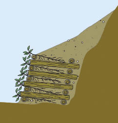
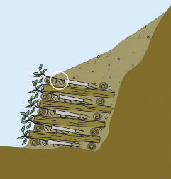
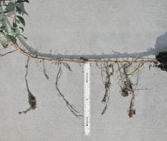
Collection — Materials for live layering are obtained from branched cuttings collected in the wild or from stooling beds. Stems up to 2 inches in diameter can be used (Sotir and Gray 1992). The basal end of the cuttings are always oriented in the same direction during collection and bundling. Cuttings for brush layers should be long enough that the growing tips are just exposed at the soil surface, while the basal portion of the cuttings reach to the back of the bench (Sotir and Gray 1992). For rock gabions, rock walls, and crib walls, cuttings should be long enough to extend into soil or backfill behind the structures. During collection, cuttings are placed in bundles and secured with twine. Bundles should be light enough to carry. The optimum period to collect cuttings is during the dormant period, when the plants have lost their leaves. If cuttings are collected outside of this period, then testing the viability of the cutting material is essential (See Section 10.2.2.4). Fine branches dry out quickly if exposed to warm dry temperatures. Cuttings must be protected during transportation, storage, and handling to avoid drying.
Storage — See discussion under Live Stakes, Section 10.3.3.2.
Installation — Branched cuttings are laid out on benches so the basal end of the cutting reaches to the back of the bench and the growing tips extend just beyond the front. Soil is placed over the cuttings and tamped to assure there are no large air spaces. Excessive compaction is unnecessary for plant establishment and is often detrimental for long-term plant growth (See Section 5.3.3). The material used to cover live branches in or behind crib walls, rock gabions, and rock walls is often low in water-holding capacity, nutrients, and organic matter. Soil amendments, such as compost, can be incorporated into backfill material to improve water-holding capacity and to serve as a long-term source of nutrients and organic matter. These amendments can increase establishment and improve plant growth (See Section 10.1.5, Organic Matter Amendments). Waiting until after the construction of crib walls, rock gabions, and rock walls to amend the soil is not practical or feasible.
10.3.3.4 Live Fascines
Live fascines are cuttings bound together to form a long continuous bundle (Figure 10.114). When installed on the contour, live fascines slow runoff, increase infiltration rate, capture sediments, reduce slope length, and revegetate the site (Sotir and Gray 1992). Live fascines have a good potential for quick establishment because of the high density of buds near the surface of the soil. Live fascines can quickly send out shoots and roots early in the growing season and become established before summer (Figure 10.114).
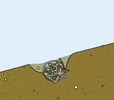
Fascines are used in the construction of live pole drains to drain saturated slopes, small slumps, or gullies (Polster 1997). Live pole drains are designed to intercept surface water from unstable slopes or seepage areas, and transmit it through a system of interconnecting bundles to more stable areas (See Section 5.7.3). The constant supply of intercepted water encourages vigorous growth of the cutting material into a continuous stand of vegetation. Fascines are also used as the base or support in the construction of modified brush layers. Live fascines have great potential for establishment because of the high density of buds just under the surface of the soil. These buds can emerge quickly in late winter and early spring. Because they are installed at the soil surface, live fascines are more prone to drying out than live brush layers or live stakes. For this reason, live fascines are more successful on moist sites or in conjunction with live brush layering or live staking.
Collection — Branches and stems up to 2 inches in diameter are collected from the wild or from stooling beds and gathered to form a long continuous bundle. Fascines vary in length from 5 to 30 ft, and from 6 to 8 inches in diameter. For large projects, constructing a series of sawhorse-type structures makes this operation easier and more efficient (Sotir and Gray 1992). At frequent intervals, bundles are secured with twine to hold the fascines together. Cuttings should be collected during the dormant season, when the plants have lost their leaves. Fine branches dry out quickly if exposed to warm dry temperatures and must be protected during transportation, storage, and handling.
Storage — See discussion under Live Stakes, Section 10.3.3.2.
Installation — Prior to installation, trenches should be created at the proper depth so the top of the fascine is flush to the surface of the slope when installed. The shape of the trench should allow soil contact with all portions of the bundle. Soil is tamped down around the sides of the bundles to assure soil contact, and the upper fifth of the bundle is covered by a thin layer (<1 inch) of soil. A very small portion of the fascine should be exposed, but not enough to dry the stems. If the fascine is buried too deeply, vegetative growth will be restricted.
10.3.4 Installing Plants
10.3.4.1 Introduction
Although a wealth of information exists about planting for reforestation, very little information has been published about planting nursery stock on roadsides. Several references can be found discussing harsh site reclamation. Ashby and Vogel (1993) is an excellent source for planting on restored minelands.
Before beginning a planting project, the revegetation plan and plant production contract should be reviewed carefully, as should the Target Seedling Concept (Figure 10.115) which was considered during the planning process (See Section 6.4). The first four steps were covered when plants were ordered during the planning process. The timing of the outplanting window and planting tools must be considered at this time.
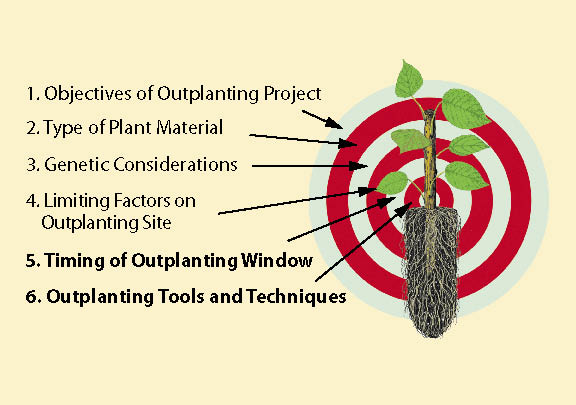
Timing of the Outplanting Window — The outplanting window is the period of time in which environmental conditions on the outplanting site are most favorable for survival and growth of nursery stock (Figure 10.116). The outplanting window is usually defined by limiting factors, and soil moisture and temperature are the usual constraints. In most of the continental United States, nursery stock is outplanted during the rains of winter or early spring when soil moisture is high and evapotranspirational losses are low. Fall outplanting is another option on some projects, especially when dormant and hardy plants can be installed just before the normal rainy season begins. Planting during the summer is usually discouraged because the nursery stock is not dormant and will experience severe transplant shock. If nursery stock is carefully handled and plants can be irrigated, then summer plantings are possible.
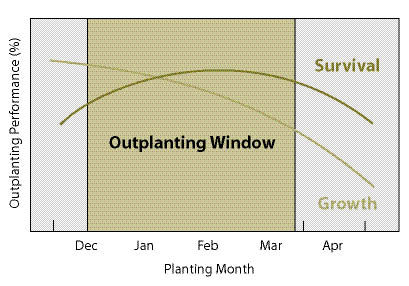
Planting Tools and Techniques — Nursery stocktype and the conditions on each outplanting site must be considered before planting begins. All too often, planters develop a preference for a particular planting implement because it has worked well in the past. However, no one tool will work for all types of nursery plants and under all site conditions. Size of nursery stock, in particular the depth and width of the root plug, is the critical consideration. Tall pots, for example, have an unusually deep root plug, which makes them difficult to plant properly with standard tools. For some types of plants and especially for large planting projects, it may be necessary to buy or rent specialized equipment, which must be secured in advance. The planting tools recommended for roadside revegetation projects are discussed in Section 10.3.4.3.
10.3.4.2 Define Planting Areas
When construction is completed, the project site is assessed for planting. A detailed map showing the exact planting locations and conditions is developed by reviewing each location on the ground. Each area should be identified on a map and described in a spreadsheet by:
- Planting area acreage,
- Planting patterns,
- Plant spacing (density),
- Survival potential, and
- Species and stocktype mix.
With this information, a planting strategy can be developed for each planting area using calculations similar to those shown in Figure 10.117.
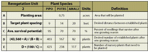
Size of Planting Areas — The first step is to measure the area of each planting unit. Although they could be calculated from blueprints, the true planting areas should be measured on-site. A practical method is described in Figure 10.118.
| Figure 10.118 — This spreadsheet is a practical way to calculate the area of each planting unit. |
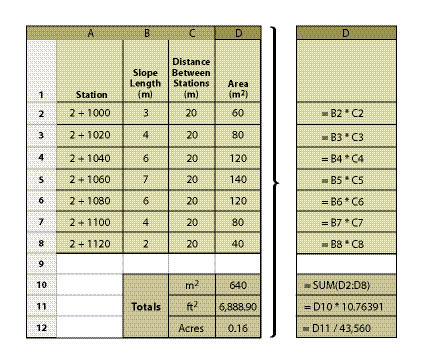 |
Planting Patterns — The pattern at which nursery stock is planted is critical for creating a more natural and visually pleasing roadside experience. Most planters have learned to install plants at uniform spacing and in rows (Figure 10.119A). Although uniform patterns ensure that all plants have equal growing space, it is not natural. Planting seedlings in groups (Figure 10.119B) or clumps (Figure 10.119C) is more visually appealing and more ecologically functional.
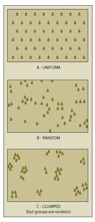
More specific considerations about planting patterns are based on project objectives and site characteristics of the area. A typical example would be using plants to screen potentially dangerous or visually sensitive areas, such as large cuts and fills or obliterated roads. Determining where trees or shrubs are to be planted to meet these objectives can only be accomplished by driving the newly constructed road and making these decisions in person.
Plant Spacing — The planting spacing or density (See Section 10.2.6.4) will determine how quickly an area will be screened by vegetation. The higher the density, the more plants are required. Selecting the appropriate density must be based on the existing vegetation density recorded at reference sites, as well as both short- and long-term project objectives. It must also be based on the expected survival rates of the planted stock, since not all planted stock will survive.
Survival Potential — Each planting area must be assessed for its unique site characteristics, such as rock content, soil depth, accessibility, steep slopes, and poor accessibility. These will determine the stocktype and species selection, method of planting, and the difficulty of transporting large plants to the site. The identified site limitations will determine the expected survival rates; target survival rates should be at least 70% to minimize the costs of site preparation and anticipated replanting.
Species Mix and Stocktype — Each planting area will have a different mix of species and stocktypes based on the site characteristics and project objectives defined during the planning stages. This is a refinement of those plans, based on site specific evaluation of the area. Trees and other large woody plants are considered "keystone species" because of their sheer size and longevity. These structurally and functionally dominant plants play a pivotal role in restoration plantings because they generate physical structure and create ecological niches for many other species. This fosters the in-seeding of other plants, resulting in a more natural and visually appealing landscape.
10.3.4.3 Select Planting Tools and Methods
One planting method will rarely work for all planting areas in a revegetation project. Roadside sites offer some serious challenges to planting nursery stock, most notably highly compacted soils and often a high percentage of rock. Road projects create the opportunity for unique situations such as planting islands.
The most common type of planting method is manual planting using a shovel. Recent developments in mechanized planting equipment have increased tools available. The most common types of planting tools for roadside revegetation sites are described below:
Shovel — The versatile "tile spade" shovel (Figure 10.120A) is the first choice for compacted soils and stocktypes used in roadside revegetation. Forestry supply companies sell a specialized planting shovel with a 14 by 5 inch blade, a welded reinforcement plate on the back of the blade (Figure 10.120B), and rubber padded footplates (Figure 10.120C). Shovels work well when planting both bareroot and container stock, as well as bulbs and other plant materials that do not require holes deeper than one foot. Working the shovel blade back and forth breaks up compacted soil and can create a planting hole for large container stock (Figure 10.120D). Sites must be accessible for hand planters, and the soils not too rocky or shallow. Very steep slopes (1:1 or greater) make shovel planting very slow and difficult.
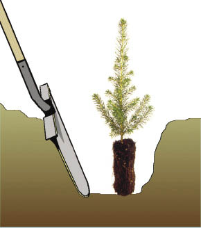
Power Auger — Power augers can be an excellent and efficient way to excavate holes for planting (Figure 10.121A). Many types of augers are available: 1-person operated, 2-person operated, and a chain saw modification. A wide variety of auger sizes means that this one implement can work for many stocktypes. Augers are particularly good for large container stock. For example, a four-inch auger bit will create planting holes that will just fit the root plug of a "Tall Pot" container plant, ensuring good root-to-soil contact (Figure 10.121B). In a comprehensive review of planting tools, Kloetzel (2004) concluded that, when container size is larger than 336 ml (20 in3), power augers will boost production under most soil conditions. It is most efficient to have one person operating the auger, with several people planting behind him/her. Auger planting is effective on restoration sites because one person determines the location and pattern of the planting holes. Production rates are reduced with rocky or compacted soils, but a drill auger with a special bit has been developed for planting large container stock in rocky soils (St. Amour 1998).
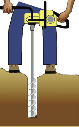
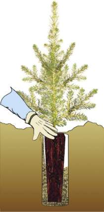
Expandable Stinger — Specialized planting equipment is needed for the rocky and steep slopes that are often found along forest roads. The original stinger was a pointed metal bar that was hydraulically forced into the soil to plant willow and cottonwood cuttings. The expandable stinger is a recently developed planting device attached to the arm of an excavator (Figure 10.122) that creates a hole and plants the seedling all in one operation. The planting head is composed of two parallel steel shafts, which are hinged in the middle to open and close in a scissor-like manner. Each shaft is constructed to create a long hollow chamber between them when closed. The opening and closing of the shafts are hydraulically driven. When the shafts are closed, the stinger comes to a point and is pushed into the soil by the force of the excavator arm. A long hardwood cutting or container plant is placed into the chamber. The expandable stinger is maneuvered to the planting spot, where the beak is inserted into the soil. When the beak opens, the seedling drops to the bottom of the hole leaving, the seedling in place (Figure 10.122B-D).
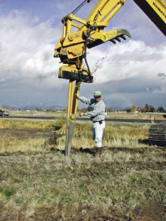
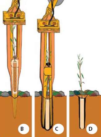
Two expandable stinger models are currently in use. The single-shot model inserts plants one at a time and averages between 50 to 80 seedlings per hour. The 50-shot model contains a rotary magazine that can hold fifty plants of up to three different species and can double the planting rate of the single-shot model (Kloetzel 2004).
The advantage of this equipment is that it can reach very steep cut and fill slopes, sites that are inaccessible by other planting methods. Smaller excavators can reach 25 feet, while larger machines extend planting up to a 50 foot radius, which is adequate for most cut and fill slopes. This equipment can also plant in very rocky soil conditions, including rip-rap and gabions, and can insert plants up to 6 feet. With the typically compacted soils on roadside sites, the action of the beak of the expandable stinger breaks up the compaction around the planting hole. While soil typically falls back around the root plug after the expandable stinger has planted the seedling, it is still important to determine whether additional soil needs to be filled and tamped around the plant. Poor soil contact with the root system can reduce survival and growth during establishment.
The major drawback to the expandable stinger is the expense. Because of the high hourly rate of an operator and equipment, the expandable stinger must be working at full capacity at all times. Good planning is essential. This means that all the planting sites are laid out before the equipment arrives, there is a clear understanding of species mix and planting for each planting area, seedlings are on the site and ready for loading into the equipment, and there is enough personnel to keep the equipment going. In a well-planned operation, the expandable stinger can plant up to 200 seedlings in an hour. In addition to the hourly operating costs, the mobilization costs can be very high, especially if the excavator and expandable stinger must be transported across several states. These costs must be spread across all seedlings being planted for a true cost. The more seedlings that are planted by the expandable stinger at one construction site, the less it will cost per planted seedling. Larger planting projects (>1,500 seedlings) spread these costs over more seedlings and make expandable stinger projects economical.
Pot Planter — The pot planter is a modification of the waterjet stinger (See Section 10.3.3, Installing Cuttings) that creates planting holes large enough for container plants. Like the waterjet stinger, it draws water from a water source (e.g., a lake, stream, water truck) and hydraulically creates a planting hole as the tip of the high pressure nozzle is pushed into the soil (Figure 10.123A). The pot planter has 3-inch vanes attached to the sides of the nozzle, which create holes large enough for containers up to one gallon (Figure 10.123B). The hole that is created by the pot planter is actually a soil slurry that is displaced when the root plug is pushed into it at the desired planting depth. Once the water drains from the slurry into the surrounding soil, the soil settles in around the root plug, assuring good soil-to-root contact.
| Figure 10.123 — The pot planter creates a planting hole by injecting high pressure water into the soil (A). Once the soil is liquefied, the container is pushed into the soil to the appropriate depth (B). | |
|
A.
|
B.
|
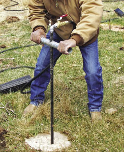
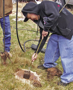
The advantages of using a pot planter include: 1) container plugs are thoroughly moistened at outplanting, 2) there are fewer air pockets in the soil and better root-to-soil contact, and 3) soil around the planting hole is moistened, allowing roots more time to move out of the plug and into the native soil. These advantages create the opportunity for earlier fall planting dates, even as early as late August to early September in some areas. The earlier the fall planting, the greater the chance for rooting to occur before winter sets in. This rooting will be in addition to the root growth that occurs the following spring and can make the difference in whether a seedling survives the first growing season. Large containers can be planted quickly at a rate of approximately one plant per minute (Hoag 2006). The pot planter is limited by the same factors as the waterjet stinger, which include steep slope gradients, inaccessibility, high soil rock content, and poor water source availability.
Planting into Engineered Structures — There are occasions when seedlings will be planted as engineered structures are being built. These structures include vegetated gabion walls, riprap, and retaining walls (See Inset 10.22 in Section 10.3.3). Planting must be well planned and integrated into the construction schedule. Since road construction often takes place in the summer when plants are in full growth, special handling methods and irrigation must be implemented during installation to assure optimum seedling establishment (Figure 10.124). Installing plants into riprap, for example, requires good planning and integration into construction activities. Drawings and a set of planting instructions are essential. Seedlings are partially planted in the existing soil and partially in riprap. Riprap and soil is hand placed around the seedling plug to assure good root—to-soil contact and that the seedlings are handled with care. The remainder of the riprap is placed and the seedlings are irrigated. Each vegetated engineered structure will require different sets of instructions and drawings that are specific to the objectives and environmental conditions of the site.
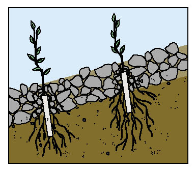
10.3.4.4 Assess Plant Inventories
Depending on the size and scope of the project, there may be many combinations of species, seedlots, and stocktypes being grown at one or more nurseries. Seedling inventories from all nurseries where your stock is being grown must be consolidated into one list. Each nursery will supply a list of the quantity of seedlings in each seedlot that meet the contract specifications. Do not be surprised if this list does not exactly meet your original order. It is rare that the original seedling order ever gets filled exactly as requested. Some seedlots grow well, while others grow poorly, and this is reflected in the seedling inventory. You will find there are more seedlings in one seedlot and less in another.
Plant inventories do not always give the full story about seedlots. Prior to putting together a planting plan, a visit to the nurseries will give a full picture of the status of each seedlot. Stressed seedlings, poor roots, root-bound seedlings, disease, and other problems can only be realized by visiting the nursery months before plants are received. The visit to the nursery is not always a negative fact finding mission. It should be approached as a problem-solving trip. For example, an inventory might indicate that certain seedlots do not meet size specifications. A closer review at the nursery may show that many of the seedlings that do not meet size specifications would be suitable in certain planting areas. If inventories are low, discussions with the nursery manager might bring up the possibilities of substituting surplus seedlots from other clients for the downfall in your inventory.
10.3.4.5 Match Inventories to Planting Area
At this point, the information developed during the location of planting units, including seedling density, species, and stocktype, must be reevaluated in light of the newest seedling inventory. In other words, the seedlings from the inventory must now be divided between planting areas in a manner that still meets the project objectives.
Using the spreadsheet in Figure 10.125 is a simple way to reconcile the differences between the plants needed at each planting area and the plant inventory. In this example, three planting areas are defined (A1, A2, and B). For each planting area the number of plants of each species/stocktype are listed. The planned needs are summarized in Line A. When the seedling inventory (Line B) is received, it is discovered that there will not be enough ponderosa pine (PIPO) or quaking aspen (POTR5) to meet the planned needs. The deficits are circled in Line C. In this example seedlings can either be obtained from other sources, or the plant needs can be adjusted downward. In this example, the PIPO and POTR5 were adjusted downward because no substitute trees could be found to make up the difference. AMAL2 (Saskatoon serviceberry) was adjusted upward as a partial substitution for the shortfall of tree seedlings. Planting spacing was recalculated from Figure 10.117 with a resulting increase of approximately 1 ft for both PIPO and POTR5. The extra PUTR2 (antelope bitterbrush) and PREM (bitter cherry) were not planted (Line F), but surplused to a local landowner. Many more rows and columns can be added to this spread sheet to accommodate more species and planting areas.
| Figure 10.125 — Spreadsheets are a handy way to keep track of nursery orders and adjust plant inventories to planting needs. |
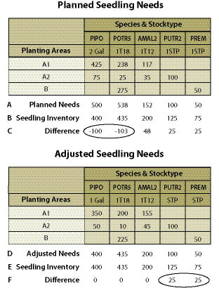 |
10.3.4.6 Transport Plants
The delivery of seedlings to the planting site is not generally the responsibility of the nursery. It can be an item in the seedling production contract, a separate transportation contract, or you can transport them yourself. Whichever way you decide, remember that seedlings can be easily damaged during transportation by poor handling, hot temperatures, or drying conditions. Plants that have been packed in bags or boxes are protected from drying conditions and can be transported in most vehicles. If containers are transported in open pickups, they should be covered with a space blanket or special tarps to moderate temperatures and minimize the potential for desiccation (Figure 10.126). Specially-constructed Mylar® tarps can be purchased from forestry or restoration supply companies.
| Figure 10.126 — During transportation and on-site storage, nursery stock should be covered with special reflective tarps (A) which have been proven to reduce temperature buildup (B). |
|
A.
|
|
B.
|
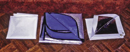
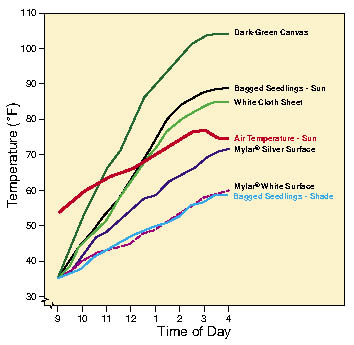
Plants that have been kept in freezer storage should be thawed prior to transportation and planting. While small container stock has been shown to have satisfactory survival when planted frozen, there is no indication that large stock will perform the same. Once frozen seedlings have been thawed or cooler-stored seedlings have been allowed to warm, they should be planted immediately. Seedling viability will decrease if they are placed back into cold storage for more than a few days.
Plants that have not been packed in storage containers must be transported in enclosed units. Transporting plants in open vehicles, such as pickups, exposes foliage to strong, drying winds which can unduly stress the plants. Large container plants typically stand 2 to 4 feet tall (including the container) and require transportation with enough space to accommodate the size.
10.3.4.7 Develop Planting Contract
The following discussion outlines some of the basic components that should be addressed in a planting contract.
Location — A map of the planting areas should be included in the contract.
Planting Quantities — The quantity of species, by stocktype, must be presented for each planting area.
Planting Method — There might be several planting methods which should be indicated for each stocktype and planting area.
Plant Spacing Requirements — For each planting area, describe or define the plant spacing at which each species will be planted. Calculations to determine the proper spacing between plants was presented in Figures 10.117. Approximate distance between plants can be determined graphically by knowing the target plants per acre, and, in reverse, the plants per acre can be determined by knowing the target spacing between plants (Figure 10.127). For example, if the plan calls for a density of 600 seedlings to be planted per acre, the spacing between plants would be around 8.5 feet (Figure 10.127A). If the plan calls 600 seedlings to be planted in planting pockets of three plants per pocket, there would be 200 planting pockets spaced approximately 15 feet apart (Figure 10.127B). In another example, if you want to know the number of seedlings to order for a given area with a target spacing of 6 feet, the number of plants required would be just under 1,100 seedlings (Figure 10.127C).
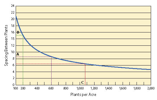
These spacing requirements are an average. Depending on the plantability of a site, the specified average spacing may vary up to 25% in any direction to find a suitable planting spot. Where an unplantable spot is encountered, the planter will plant in the closest plantable spot. Whenever possible, plants should be installed next to stumps, logs, or other obstacles that provide partial protection from sun, wind, and animals. If planting islands are designed into the planting areas, each island should be marked within the planting area by the contract inspector and the species mix should be stated in the contract.
Handling Care — Plants must be handled with care to prevent damage to roots and foliage. Seedlings must not be thrown, dropped, hit, or otherwise mechanically impacted. Extracting the root plug from the container must be done gently, avoiding excessive force when pulling the seedling from the container. Seedlings should not be removed from containers until the hole is excavated. The container is then removed, and the seedling is quickly planted. Excessive exposure of the root system to the air will decrease seedling survival and growth (Greaves and Hermann 1978).
Root Pruning — The bottoms of some containers are poorly designed, causing roots to circle or build up at the bottom of the pot (Figure 10.128A). These damaged roots must be cut prior to planting to prevent potential root strangling, especially for tap-rooted woody species (Figure 10.128B). Root pruning is best accomplished at the nursery, but must be stated in the growing contract to cover the added expense. Pruning in the field is not recommended because of the increased root exposure. However, it may be necessary when nursery stock arrives with constricted roots.
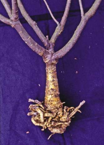
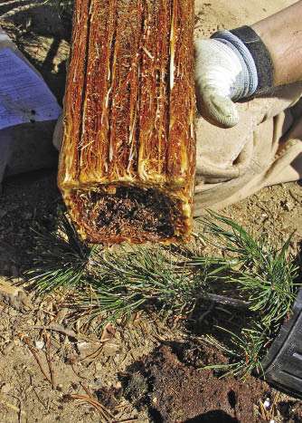
Container Moisture — Root plugs that are dry must be thoroughly moistened prior to planting. Irrigating seedlings at the nursery several days before shipping and again on the day of shipping assures that root plugs are completely wet. These instructions must be conveyed to the nursery manager prior to picking up the seedlings. Provisions should be in the contract that addresses the need for wetting root systems should they be dry at the time of planting. Wetting root plugs can be accomplished by dipping seedling containers into a large water container, such as a cattle trough or trash can, prior to planting. Planting seedlings using the pot planter assures that the root plugs are wet at planting.
Temporary Storage — If container plants cannot be planted in one day, they can be stored in the field in a well-sheltered area protected from the sun and animals. Reflective tarps are recommended to keep plants cool and moist during on-site storage (Figure 10.126). If container plants are left out for several days, the root plug should not be allowed dry out. If they do lose moisture, the containers must be irrigated prior to planting. Plants that have been extracted and placed in storage boxes or bags should not be left on—site, but returned to a local cooler for storage.
Planting — Prior to preparing the planting hole, the planters must clear the surface of the planting spot of all limbs, logs, snow, duff, litter, rocks, and other loose debris. If sod, crowns of living plants, and roots are present, they must be scalped down to moist mineral soils. Clearing and scalping dimensions must be stated in the contract. Planting holes shall be located near the center of the prepared planting spot and they should be dug vertically rather than perpendicular to the ground surface. The planting hole should be three to four inches deeper than the total length of the root system or root plug, and wide enough to fully accommodate the width of the root system. Seedlings should be placed in the hole so that the cotyledon scar (the bump or constricted area on the seedling stem that is the transition from the root system to the stem) is one inch below the ground line. Species that can be rooted from cuttings can be planted deeper, since portions of the stem will root when buried. The root plugs should not be forced into the planting hole, distorted, or broken during planting. After placing the plant in the hole, excavated soil is placed firmly around the root system so there is no loose soil or air pockets around the root plug. The root system must not be damaged during this operation. A small circular water-holding basin can be created around each seedling after planting to capture water or store irrigation water.
10.3.4.8 Administer Contract
The planting contract inspector must 1) schedule the shipment of seedlings from the nursery, 2) be certain that root plugs are moist and ready for planting, 3) have the right quantities of plants at each planting area, and 4) inspect the contract. In addition, if there are special planting patterns designed for the planting area, these may need to be marked on the site prior to planting.
The planting inspector must determine if the conditions are favorable for planting. Seedlings should not be planted into dry soil unless the planting spot is irrigated immediately after planting or the pot planter method is being used. Under certain circumstances, high moisture soils follow geomorphic features, such as creek or river terraces where high ground water brings moisture to the soil surface. These sites should be identified on the ground at the time of planting.
10.3.4.9 Monitor Planting Success
Valuable information can be gained by monitoring nursery stock for several years after planting. The first few months are critical because nursery plants that die immediately after outplanting indicate a problem with nursery stock quality. Plants that survive initially, but gradually lose vigor, indicate poor planting or drought conditions. Therefore, plots must be monitored during and at the end of the first year for initial survival. Subsequent checks after 3 years will give a good indication of plant growth potential (Figure 10.129). This performance information is then used to give valuable feedback to the nursery manager, who can fine-tune the target specifications for the next crop.
| Figure 10.129 — Monitoring the survival and growth of nursery stock for several years after planting provides valuable information for future projects. |
 |